McAfee M-1250 Network Protection - Page 15
Cable the Fast Ethernet monitoring ports, Cable a failover pair, Gigabit Copper Fail-Open Kit Guide
 |
View all McAfee M-1250 manuals
Add to My Manuals
Save this manual to your list of manuals |
Page 15 highlights
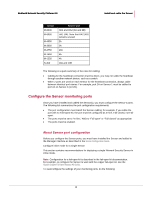
McAfee® Network Security Platform 6.0 Install and cable the Sensor Cable the Fast Ethernet monitoring ports The FE ports available on some Sensor models fail-open and require no extra hardware; simply connect your cables to a port pair (For example: 1A-1B). Fail-closed mode for FE ports requires use of the fail-closed dongles on each connecting cable of the port pair. The fail-closed dongles provided with the Sensor are designed to complement 10/100 monitoring port functionality. You plug the dongles into a Sensor's 10/100 monitoring port, and then connect a Cat 5/Cat 5e cable to the dongles. Cable the Gigabit Ethernet monitoring ports Fail-Open mode for Gigabit Ethernet (GE) ports requires use of the external Gigabit Failopen Kit. This kit includes a Gigabit Bypass Switch and an adaptor that connects the switch to the Sensor. Note: Fail-closed mode for GE ports requires no extra hardware; simply connect your fiber cables to the GE port pair (For example: 1A-1B). For information on how to cable the Sensor with a Gigabit Fail-Open Kit, see the documentation that accompanies the kit. For example, the Gigabit Copper Kit includes the Gigabit Copper Fail-Open Kit Guide. Cable a failover pair Failover requires connecting the paired Sensors via an interconnection cable or cables. Communication between paired Sensors maintains the failover heartbeat and state information. There is no standard heartbeat port across all the Sensor models. The port or ports you use to connect the two Sensors depends on the Sensor model. The Sensor models and their failover interconnection ports are described below. Sensor I-4010 I-4000 I-3000 I-2700 I-1400 I-1200 Failover port HA1 and HA2 (6A and 6B) 2A and 2B HA1 and HA2 (6A and 6B) 4A Response port 1 (R1) Response port 1 (R1) 7
-
 1
1 -
2
-
3
-
4
-
5
-
6
-
7
-
8
-
9
-
 10
10 -
 11
11 -
 12
12 -
 13
13 -
 14
14 -
 15
15 -
 16
16 -
 17
17 -
 18
18 -
 19
19 -
 20
20 -
21
-
22
-
23
-
24
-
25
-
26
-
27
-
28
-
29
-
30
-
31
-
32
 |
 |
