Metabo BE 1100 Operating Instructions 2 - Page 10
English - plus
 |
View all Metabo BE 1100 manuals
Add to My Manuals
Save this manual to your list of manuals |
Page 10 highlights
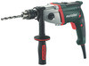
en ENGLISH Caution left-handed thread ! (see Section 8.7.) both hands using the handles provided, stand in a safe position and concentrate. 6.1 Assembly of additional handle (2) For safety reasons, always use the additional handle supplied. Open the clamping ring by turning the additional handle (2) counter-clockwise. Push the additional handle onto the collar of the machine. Slide the additional handle far enough forward so that it can be turned. At the desired angle, pull it back and tighten firmly. 7. Use 7.1 Setting direction of rotation, transport lock (switch-on lock) Do not activate the rotation selector switch (7) unless the motor has completely stopped. See page 2. R = Clockwise setting L = Counter-clockwise setting 0 = Central position: transport lock setting (switch-on lock) The drill chuck must be firmly screwed onto the spindle and the safety screw inside the drill chuck (if applicable / model-specific) must be firmly tightened with a screwdriver. (Caution, left-handed thread !) If rotated counterclockwise (e.g. when screwing) it could otherwise become loose. 7.2 Selecting a gear Select the desired gear by turning the thumbwheel (1). Change speed only when the machine is in the process of running down (briefly switch it on and off). 1st gear (low speed, high torque) e.g. for screwdriving, drilling 2nd gear (high speed) e.g. for drilling 7.3 Preselect speed Use the setting wheel (5) to preselect the maximum speed. See page 4 for recommended drilling speeds. 7.4 Switching on/off, changing speed Switching on, speed: press the trigger (9). The speed can be changed by pressing in the trigger. The electronic soft start means that the machine accelerates continuously until the preselected speed is reached. Release the trigger to switch off. Continuous activation: While pressing on the trigger (9), press in the locking button (8) and then release the trigger. To switch off, press and release the trigger (9) again. In continuous operation, the machine continues running if it is forced out of your 10 hands. Therefore, always hold the machine with 7.5 Tool change with Plus (4) chuck See illustrations A, page 2. Opening the drill chuck: Using one hand, hold the retaining ring securely (depending on equipment, not necessary for BE 1300 Quick) and, using the other hand, turn the sleeve in the direction of the arrow -1. The ratchet sound which can possibly be heard after opening the drill chuck is functional and is switched off by a reverse rotation of the sleeve. BE 751, BE 1100: If the chuck is very securely tightened: Unplug. Hold the chuck using an open-end spanner at the flats on its head, and turn the sleeve vigorously in the direction of the arrow -1. Clamping the tool - Insert the tool -2- as far as possible. - Using one hand, hold the retainer ring securely (depending on equipment; not required for BE 1300 Quick). - Turn sleeve in direction -3- until the noticeable mechanical resistance has been overcome. - Caution! The tool is not yet fully tightened! Keep turning the sleeve (it must "click" when turning) until it cannot be turned any further - only now is the tool safely clamped. With a soft tool shank, retightening may be required after a short period of operation. 7.6 Tool change with a geared chuck (3) See illustrations B on page 2. Opening the drill chuck: Open the geared chuck with chuck key -1. Clamping the tool: Insert tool -2- as far as possible and, using the chuck key, evenly secure in all 3 bores -3. 7.7 Drill chuck with "Quick" change system (for BE 1300 Quick) See illustration on page 2. To remove: Push the interlock ring forward (a), advance and pull off the chuck (b). To mount: Push the interlock ring forward and move the chuck as far as the limit stop on the drill spindle (slightly turn the chuck if necessary). 7.8 Unscrewing chuck (when screwing without chuck or when using attachments) See illustrations Y, Z on the second last page. Note for illus. Y, Z: Release by tapping lightly with a rubber hammer, as shown, and unscrew. Note: If a bit clamping bush (order no. 6.31281) is attached, the screwdriver bit inserted in the hexagon socket of the spindle is held in place.
-
 1
1 -
2
-
3
-
4
-
 5
5 -
 6
6 -
 7
7 -
 8
8 -
 9
9 -
 10
10 -
 11
11 -
 12
12 -
 13
13 -
 14
14 -
 15
15 -
16
-
17
-
18
-
19
-
20
-
21
-
22
-
23
-
24
-
25
-
26
-
27
-
28
-
29
-
30
-
31
-
32
-
33
-
34
-
35
-
36
-
37
-
38
-
39
-
40
-
41
-
42
-
43
-
44
-
45
-
46
-
47
-
48
-
49
-
50
-
51
-
52
-
53
-
54
-
55
-
56
-
57
-
58
-
59
-
60
 |
 |
