Netgear FVX538 FVX538 Reference Manual - Page 22
Router Front Panel, Warranty and Support Information Card. - factory reset
 |
UPC - 606449037234
View all Netgear FVX538 manuals
Add to My Manuals
Save this manual to your list of manuals |
Page 22 highlights
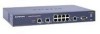
ProSafe VPN Firewall 200 FVX538 Reference Manual • 19-inch rack mounting hardware and rubber feet. • Category 5 (Cat5) Ethernet cable. • Installation Guide, FVX538 ProSafe VPN Firewall 200 • Resource CD, including: - Application Notes and other helpful information. - ProSafe VPN Client Software - five user licenses. - Trend Micro software evaluation. • Warranty and Support Information Card. If any of the parts are incorrect, missing, or damaged, contact your NETGEAR dealer. Keep the carton, including the original packing materials, in case you need to return the firewall for repair. Router Front Panel The ProSafe VPN Firewall 200 front panel shown below contains the port connections, status LEDs, and the factory defaults reset button. 1 2 3 4 5 6 7 Figure 1-1 Table 1-1 describes each item on the front panel and its operation. Table 1-1. Object Descriptions Object Activity 1. Power LED On (Green) Off On (Amber) 2. Test LED Blinking (Amber) Off Description Power is supplied to the firewall. Power is not supplied to the firewall. Test mode: The system is initializing or the initialization has failed. Writing to Flash memory (during upgrading or resetting to defaults). The system has booted successfully. 1-6 Introduction v1.0, August 2006
-
 1
1 -
2
-
3
-
4
-
5
-
6
-
7
-
8
-
9
-
10
-
11
-
12
-
13
-
14
-
15
-
16
-
 17
17 -
 18
18 -
 19
19 -
 20
20 -
 21
21 -
 22
22 -
 23
23 -
 24
24 -
 25
25 -
 26
26 -
 27
27 -
28
-
29
-
30
-
31
-
32
-
33
-
34
-
35
-
36
-
37
-
38
-
39
-
40
-
41
-
42
-
43
-
44
-
45
-
46
-
47
-
48
-
49
-
50
-
51
-
52
-
53
-
54
-
55
-
56
-
57
-
58
-
59
-
60
-
61
-
62
-
63
-
64
-
65
-
66
-
67
-
68
-
69
-
70
-
71
-
72
-
73
-
74
-
75
-
76
-
77
-
78
-
79
-
80
-
81
-
82
-
83
-
84
-
85
-
86
-
87
-
88
-
89
-
90
-
91
-
92
-
93
-
94
-
95
-
96
-
97
-
98
-
99
-
100
-
101
-
102
-
103
-
104
-
105
-
106
-
107
-
108
-
109
-
110
-
111
-
112
-
113
-
114
-
115
-
116
-
117
-
118
-
119
-
120
-
121
-
122
-
123
-
124
-
125
-
126
-
127
-
128
-
129
-
130
-
131
-
132
-
133
-
134
-
135
-
136
-
137
-
138
-
139
-
140
-
141
-
142
-
143
-
144
-
145
-
146
-
147
-
148
-
149
-
150
-
151
-
152
-
153
-
154
-
155
-
156
-
157
-
158
-
159
-
160
-
161
-
162
-
163
-
164
-
165
-
166
-
167
-
168
-
169
-
170
-
171
-
172
-
173
-
174
-
175
-
176
-
177
-
178
-
179
-
180
-
181
-
182
-
183
-
184
-
185
-
186
-
187
-
188
-
189
-
190
-
191
-
192
-
193
-
194
-
195
-
196
-
197
-
198
-
199
-
200
-
201
-
202
-
203
-
204
-
205
-
206
-
207
-
208
-
209
-
210
-
211
-
212
-
213
-
214
-
215
-
216
-
217
-
218
-
219
-
220
-
221
-
222
 |
 |
