Netgear GS728TP GS728TP/GS728TPP/GS752TP Software Administration Manual - Page 269
Enable, APPLY, MST ID, Priority, VLAN ID, CST Port Configuration
 |
View all Netgear GS728TP manuals
Add to My Manuals
Save this manual to your list of manuals |
Page 269 highlights
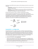
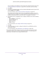
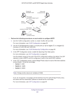
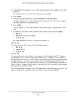
GS752TP, GS728TP, and GS728TPP Gigabit Smart Switches 5. In the CST Port Configuration screen, select ports g1-g8 and select Enable from the STP Status list. For more information, see CST Port Configuration on page 96. 6. Click APPLY. 7. Select ports g1-g5 (edge ports), and select Enable from the Fast Link list. Since the edge ports are not at risk for network loops, ports with Fast Link are enabled transition directly to the forwarding state. 8. Click APPLY. You can use the CST Port Status screen to view spanning tree information about each port. 9. In the MST Configuration screen, create an MST instance with the following settings: • MST ID. 1 • Priority. Use the default (32768) • VLAN ID. 300 For more information, see MST Configuration on page 100. 10. Click Add. 11. Create a second MST instance with the following settings: • MST ID. 2 • Priority. 49152 • VLAN ID. 500 12. Click Add. In this example, assume that Switch 1 has become the Root bridge for the MST instance 1, and Switch 2 has become the Root bridge for MST instance 2. Switch 3 has hosts in the Sales department (ports g1, g2, and g3) and in the Human Resources department (ports g4 and g5). Switches 1 and 2 also have hosts in the Sales and HR departments. The hosts connected from Switch 2 use VLAN 500, MST instance 2 to communicate with the hosts on Switch 3 directly. Likewise, hosts of Switch 1 use VLAN 300, MST instance 1 to communicate with the hosts on Switch 3 directly. The hosts use different instances of MSTP to effectively use the links across the switch. The same concept can be extended to other switches and more instances of MSTP. Configuration Examples 269
-
 1
1 -
2
-
3
-
4
-
5
-
6
-
7
-
8
-
9
-
10
-
11
-
12
-
13
-
14
-
15
-
16
-
17
-
18
-
19
-
20
-
21
-
22
-
23
-
24
-
25
-
26
-
27
-
28
-
29
-
30
-
31
-
32
-
33
-
34
-
35
-
36
-
37
-
38
-
39
-
40
-
41
-
42
-
43
-
44
-
45
-
46
-
47
-
48
-
49
-
50
-
51
-
52
-
53
-
54
-
55
-
56
-
57
-
58
-
59
-
60
-
61
-
62
-
63
-
64
-
65
-
66
-
67
-
68
-
69
-
70
-
71
-
72
-
73
-
74
-
75
-
76
-
77
-
78
-
79
-
80
-
81
-
82
-
83
-
84
-
85
-
86
-
87
-
88
-
89
-
90
-
91
-
92
-
93
-
94
-
95
-
96
-
97
-
98
-
99
-
100
-
101
-
102
-
103
-
104
-
105
-
106
-
107
-
108
-
109
-
110
-
111
-
112
-
113
-
114
-
115
-
116
-
117
-
118
-
119
-
120
-
121
-
122
-
123
-
124
-
125
-
126
-
127
-
128
-
129
-
130
-
131
-
132
-
133
-
134
-
135
-
136
-
137
-
138
-
139
-
140
-
141
-
142
-
143
-
144
-
145
-
146
-
147
-
148
-
149
-
150
-
151
-
152
-
153
-
154
-
155
-
156
-
157
-
158
-
159
-
160
-
161
-
162
-
163
-
164
-
165
-
166
-
167
-
168
-
169
-
170
-
171
-
172
-
173
-
174
-
175
-
176
-
177
-
178
-
179
-
180
-
181
-
182
-
183
-
184
-
185
-
186
-
187
-
188
-
189
-
190
-
191
-
192
-
193
-
194
-
195
-
196
-
197
-
198
-
199
-
200
-
201
-
202
-
203
-
204
-
205
-
206
-
207
-
208
-
209
-
210
-
211
-
212
-
213
-
214
-
215
-
216
-
217
-
218
-
219
-
220
-
221
-
222
-
223
-
224
-
225
-
226
-
227
-
228
-
229
-
230
-
231
-
232
-
233
-
234
-
235
-
236
-
237
-
238
-
239
-
240
-
241
-
242
-
243
-
244
-
245
-
246
-
247
-
248
-
249
-
250
-
251
-
252
-
253
-
254
-
255
-
256
-
257
-
258
-
259
-
260
-
261
-
262
-
263
-
 264
264 -
 265
265 -
 266
266 -
 267
267 -
 268
268 -
 269
269 -
 270
270 -
 271
271 -
 272
272 -
 273
273 -
 274
274 -
275
 |
 |