Netgear SW510 Installation Guide - Page 13
Physical Description, Front Panel
 |
UPC - 606449000955
View all Netgear SW510 manuals
Add to My Manuals
Save this manual to your list of manuals |
Page 13 highlights
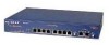
Chapter 2 Physical Description This chapter explains the hardware features of the NETGEAR Model SW510 and Model SW518 Ethernet switches. It is divided into sections explaining the front and rear panels of the switches. Use the key at the bottom of each illustration to identify the panel components. Front Panel For easier management and control of the switches, familiarize yourself with the ports, LEDs, and Normal/Uplink push button switches, as illustrated in Figure 2-1 and Figure 2-2 showing the front panels of the switches. 1 2 3 4 5 6 7 10 PORT 10/100Mbps Ethernet Switch 10/100 Mbps MODELSW510 10/100 Mbps Link 1 FDX 2 3 4 100Mbps 5 6 7 8 Link 9 FDX Link 10 FDX Normal/Uplink Normal/Uplink Power 1 2 3 4 5 6 7 8 9 10 Green = Rx/Tx Yellow = Collision Key: 1 = Power LED 2 = Rx/Tx and Collision LEDs for ports 1 through 10 3 = 100 Mbps LEDs for ports 9 and 10 4 = 10 Mbps Ethernet ports1 through 8 with Link and FDX LEDs on each port 5 = Normal/Uplink push button to configure port 8 6 = 10/100 Mbps Ethernet ports 9 and 10 with Link and FDX LEDs on each port 7 = Normal/Uplink push button to configure port 10 592EA Figure 2-1. Front panel of the Model SW510 switch Physical Description 2-1
-
 1
1 -
2
-
3
-
4
-
5
-
6
-
7
-
 8
8 -
 9
9 -
 10
10 -
 11
11 -
 12
12 -
 13
13 -
 14
14 -
 15
15 -
 16
16 -
 17
17 -
 18
18 -
19
-
20
-
21
-
22
-
23
-
24
-
25
-
26
-
27
-
28
-
29
-
30
-
31
-
32
-
33
-
34
-
35
-
36
-
37
-
38
-
39
-
40
-
41
-
42
 |
 |
