Oki OKIPAGE10i Flash Simm Hardware Installation Guide - Page 10
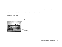
Pivot the SIMM to the left until it snaps into place.
 |
View all Oki OKIPAGE10i manuals
Add to My Manuals
Save this manual to your list of manuals |
Page 10 highlights
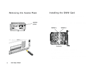
2 Insert the silver metallic contact edge of the SIMM into the left socket (FSIMM1) at about a 45° angle, with the notched corner of the SIMM at the bottom. Push in until the silver contacts are fully inserted into the socket. 4 Insert the tabs on the metal plate into the slots on the printer housing, then swing it up into place and replace the two mounting screws. 3 Pivot the SIMM to the left until it snaps into place. |10 OKI Flash SIMM
-
 1
1 -
2
-
3
-
4
-
 5
5 -
 6
6 -
 7
7 -
 8
8 -
 9
9 -
 10
10 -
 11
11 -
 12
12 -
 13
13 -
 14
14 -
 15
15 -
16
-
17
-
18
-
19
 |
 |

10
OKI Flash SIMM
|
2
Insert the silver metallic contact edge of the SIMM into
the left socket (FSIMM1) at about a 45° angle, with the
notched corner of the SIMM at the bottom.
Push in until
the silver contacts are fully inserted into the socket.
3
Pivot the SIMM to the left until it snaps into place.
4
Insert the tabs on the metal plate into the slots on the
printer housing, then swing it up into place and replace
the two mounting screws.