Oki OkiPOS406 OkiPOS406 Users Guide - Page 107
Appendix C: Parallel Interface, Table of Connection Signals for Each Mode
 |
View all Oki OkiPOS406 manuals
Add to My Manuals
Save this manual to your list of manuals |
Page 107 highlights
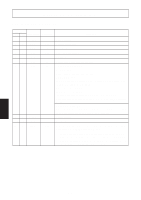
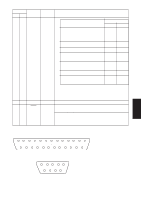
Appendix C: Parallel Interface The two-way parallel interface is compatible with the IEEE1284 compatibility mode, nibble mode and byte mode. Refer to the separate programmer's manual for details. Table of Connection Signals for Each Mode Pin No. 1 2 3 4 5 6 7 8 9 10 11 12 13 14 15 16 17 18 19~30 31 32 33 34 35 36 Direction In In/Out In/Out In/Out In/Out In/Out In/Out In/Out In/Out Out Out Out Out In OUT In Out Out In Compatibility Mode Signal Name nStrobe Data0 Data1 Data2 Data3 Data4 Data5 Data6 Data7 nAck Busy PError Select - - Signal GND Frame GND +5V Twisted Pair Return nInit nFault External GND Compulsion Status - nSelectIn Nibble Mode Signal Name Host Clock Data0 Data1 Data2 Data3 Data4 Data5 Data6 Data7 PtrClk PtrBusy/Data3,7 AckDataReq/Data2,6 Xflag/Data1,5 HostBusy - Signal GND Frame GND +5V Twisted Pair Return nInit nDataAvail/Data0,4 - - - 1284Active Byte Mode Signal Name Host Clock Data0 Data1 Data2 Data3 Data4 Data5 Data6 Data7 PtrClk PtrBusy AckDataReq Xflag HostBusy - Signal GND Frame GND +5V Twisted Pair Return nInit nDataAvail - - - 1284Active APPENDIX This connector mates with an Amphenol 57-30360 connector Parallel interface connector (printer side) - 104 -
-
 1
1 -
2
-
3
-
4
-
5
-
6
-
7
-
8
-
9
-
10
-
11
-
12
-
13
-
14
-
15
-
16
-
17
-
18
-
19
-
20
-
21
-
22
-
23
-
24
-
25
-
26
-
27
-
28
-
29
-
30
-
31
-
32
-
33
-
34
-
35
-
36
-
37
-
38
-
39
-
40
-
41
-
42
-
43
-
44
-
45
-
46
-
47
-
48
-
49
-
50
-
51
-
52
-
53
-
54
-
55
-
56
-
57
-
58
-
59
-
60
-
61
-
62
-
63
-
64
-
65
-
66
-
67
-
68
-
69
-
70
-
71
-
72
-
73
-
74
-
75
-
76
-
77
-
78
-
79
-
80
-
81
-
82
-
83
-
84
-
85
-
86
-
87
-
88
-
89
-
90
-
91
-
92
-
93
-
94
-
95
-
96
-
97
-
98
-
99
-
100
-
101
-
 102
102 -
 103
103 -
 104
104 -
 105
105 -
 106
106 -
 107
107 -
 108
108 -
 109
109 -
 110
110 -
 111
111 -
 112
112 -
113
 |
 |
