Oki OkiPOS406 OkiPOS406 Users Guide - Page 111
Appendix E: Periheral Unit Drive Circuit, Peripheral Drive Connector
 |
View all Oki OkiPOS406 manuals
Add to My Manuals
Save this manual to your list of manuals |
Page 111 highlights
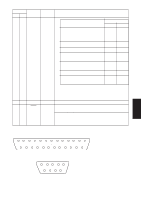
Appendix E: Periheral Unit Drive Circuit Peripheral unit drive circuit connector only connects to peripheral units such as cash drawers, etc. Do not connect it to a telephone. Use cables which meet the following specifications. Peripheral Drive Connector Pin No. Signal name 1 FG 2 DRD1 3 +24V 4 +24V 5 DRD2 6 DRSNS Function Frame ground Drive signal 1 Drive power Drive power Drive signal 2 Sense signal I/O direction - OUT OUT OUT OUT IN 6 1 Modular plug Modular plug: MOLEX 90075-0007, AMP641337, or BURNDY B-66-4 Shield Wire lead APPENDIX 6 1 Notes: 1. Pin 1 must be shield drain wire connected to peripheral device frame ground. 2. It is not possible to drive two drives simultaneously. 3. The peripheral drive duty must satisfy the following: ON time / (ON time + OFF time) ≤ 0.2 4. The resistance of the peripheral drive solenoid must be 24 Ω or higher. If it is lower than 24 Ω, over-current may flow into the solenoid, causing the solenoid to burn. - 108 -
-
 1
1 -
2
-
3
-
4
-
5
-
6
-
7
-
8
-
9
-
10
-
11
-
12
-
13
-
14
-
15
-
16
-
17
-
18
-
19
-
20
-
21
-
22
-
23
-
24
-
25
-
26
-
27
-
28
-
29
-
30
-
31
-
32
-
33
-
34
-
35
-
36
-
37
-
38
-
39
-
40
-
41
-
42
-
43
-
44
-
45
-
46
-
47
-
48
-
49
-
50
-
51
-
52
-
53
-
54
-
55
-
56
-
57
-
58
-
59
-
60
-
61
-
62
-
63
-
64
-
65
-
66
-
67
-
68
-
69
-
70
-
71
-
72
-
73
-
74
-
75
-
76
-
77
-
78
-
79
-
80
-
81
-
82
-
83
-
84
-
85
-
86
-
87
-
88
-
89
-
90
-
91
-
92
-
93
-
94
-
95
-
96
-
97
-
98
-
99
-
100
-
101
-
102
-
103
-
104
-
105
-
 106
106 -
 107
107 -
 108
108 -
 109
109 -
 110
110 -
 111
111 -
 112
112 -
 113
113
 |
 |
