Optoma ZU725TST Manual - Page 11
Optional accessories, Product Overview, Power Socket / Power Switch
 |
View all Optoma ZU725TST manuals
Add to My Manuals
Save this manual to your list of manuals |
Page 11 highlights
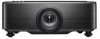
INTRODUCTION Product Overview 2 1 3 4 5 6 7 5 Minimum 500mm (19.69") 8 9 5 6 6 10 11 5 12 Minimum 500mm (19.69") Minimum 500mm (19.69") Note: ‡ ‡ Do not block projector intake and exhaust vents. When operating the projector in an enclosed space, allow at least 500mm (19.69") clearance around the intake and exhaust vents. No. Item 1. IR Receiver 2. Ventilation (Outlet) 3. LED Indicators 4. Deco Ring (1.6x lens / 1.26x lens models) 5. Tilt-Adjustment Foot 6. Ventilation (Inlet) No. Item 7. Projection Lens 8. Input / Output 9. Kensington™ Lock Port 10. Control Panel 11. Power Socket / Power Switch 12. Speakers English 11
-
 1
1 -
2
-
3
-
4
-
5
-
 6
6 -
 7
7 -
 8
8 -
 9
9 -
 10
10 -
 11
11 -
 12
12 -
 13
13 -
 14
14 -
 15
15 -
 16
16 -
17
-
18
-
19
-
20
-
21
-
22
-
23
-
24
-
25
-
26
-
27
-
28
-
29
-
30
-
31
-
32
-
33
-
34
-
35
-
36
-
37
-
38
-
39
-
40
-
41
-
42
-
43
-
44
-
45
-
46
-
47
-
48
-
49
-
50
-
51
-
52
-
53
-
54
-
55
-
56
-
57
-
58
-
59
-
60
-
61
-
62
-
63
-
64
-
65
-
66
-
67
-
68
-
69
-
70
-
71
-
72
-
73
-
74
-
75
-
76
-
77
-
78
-
79
-
80
-
81
-
82
-
83
-
84
-
85
-
86
-
87
-
88
-
89
-
90
-
91
-
92
 |
 |

English
11
INTRODUCTION
Product Overview
7
6
6
6
3
5
5
11
4
5
8
5
2
1
10
9
12
Minimum
500mm (19.69”)
Minimum
500mm (19.69”)
Minimum
500mm (19.69”)
Note:
±
Do not block projector intake and exhaust vents
.
±
When operating the projector in an enclosed space, allow at least 500mm (19.69”) clearance around
the intake and exhaust vents.
No.
Item
No.
Item
1.
IR Receiver
7.
Projection Lens
2.
Ventilation (Outlet)
8.
Input / Output
3.
LED Indicators
9.
Kensington™ Lock Port
4.
Deco Ring
(1.6x lens / 1.26x lens models)
10.
Control Panel
5.
Tilt-Adjustment Foot
11.
Power Socket / Power Switch
6.
Ventilation (Inlet)
12.
Speakers