Panasonic AJD455 AJD455 User Guide - Page 10
: The AJ-YA455P serial interface board optional accessory is necessary.
 |
View all Panasonic AJD455 manuals
Add to My Manuals
Save this manual to your list of manuals |
Page 10 highlights
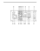
Controls and their functions #2 DIAG button When this is pressed, VTR information is displayed. When it is pressed again, the original display is restored. There are two types of VTR information: "HOURS METER" information and "WARNING" information. Switching between these types is enabled by pressing the cursor buttons ( , ). Indicated on the "HOUR METER" screen are the power-on time, drum rotation time, tape travel time, loading count, etc. Indicated on the "WARNING" screen are the warnings. • The status information on the IEEE1394 interface can be referenced when the AJ-YAD455P digital video interface board is used. #3 VIDEO INPUT switch This switches the video input signal. DVCPRO/DV: Set to this position when recording digital video interface signals (IEEE1394). (At the same time, audio input signals from IEEE1394 will also be recorded.)*1 SDI: For selecting serial component digital video signal (SMPTE 259M-C) recording.*2 ANALOG: For selecting analog video signal recording. Select the analog video signal as follows to correspond with the input signal. Y PB PR: For recording an analog component video signal. CMPST: For recording an analog composite video signal. S-VIDEO: For recording a S-VIDEO signal. *1: The AJ-YAD455P digital video interface board (optional accessory) is required for this. *2: The AJ-YA455P serial interface board (optional accessory) is necessary. #4 AUDIO INPUT switch This switches the audio input signal. SDI: For selecting serial digital audio signal (SMPTE 272M-A) recording.* AES/EBU: For recording a digital audio signal. ANALOG: For recording an analog audio signal. * The AJ-YA455P serial interface board (optional accessory) is required for this. • The DVCPRO/DV format will also apply to the audio input signals when DVCPRO/DV has been selected by the VIDEO INPUT switch #3. • When SD or AES/EBU is to be selected, the reference video signal must be input, and the audio data synchronized with the REF VIDEO signal must be supplied. #5 REMOTE/LOCAL switch This is set to control the unit from an external component using the REMOTE, RS-232C or digital video interface (IEEE1394) connector. REMOTE: Set here to control the unit by a component connected to the unit using the 9-pin REMOTE, RS-232C or digital video interface (IEEE1394) connector. LOCAL: Set here to control the unit using the switches and controls on the unit's control panel. 10
-
 1
1 -
2
-
3
-
4
-
 5
5 -
 6
6 -
 7
7 -
 8
8 -
 9
9 -
 10
10 -
 11
11 -
 12
12 -
 13
13 -
 14
14 -
 15
15 -
16
-
17
-
18
-
19
-
20
-
21
-
22
-
23
-
24
-
25
-
26
-
27
-
28
-
29
-
30
-
31
-
32
-
33
-
34
-
35
-
36
-
37
-
38
-
39
-
40
-
41
-
42
-
43
-
44
-
45
-
46
-
47
-
48
-
49
-
50
-
51
-
52
 |
 |
