Panasonic AJD455 AJD455 User Guide - Page 22
USER menu, <BASIC>
 |
View all Panasonic AJD455 manuals
Add to My Manuals
Save this manual to your list of manuals |
Page 22 highlights
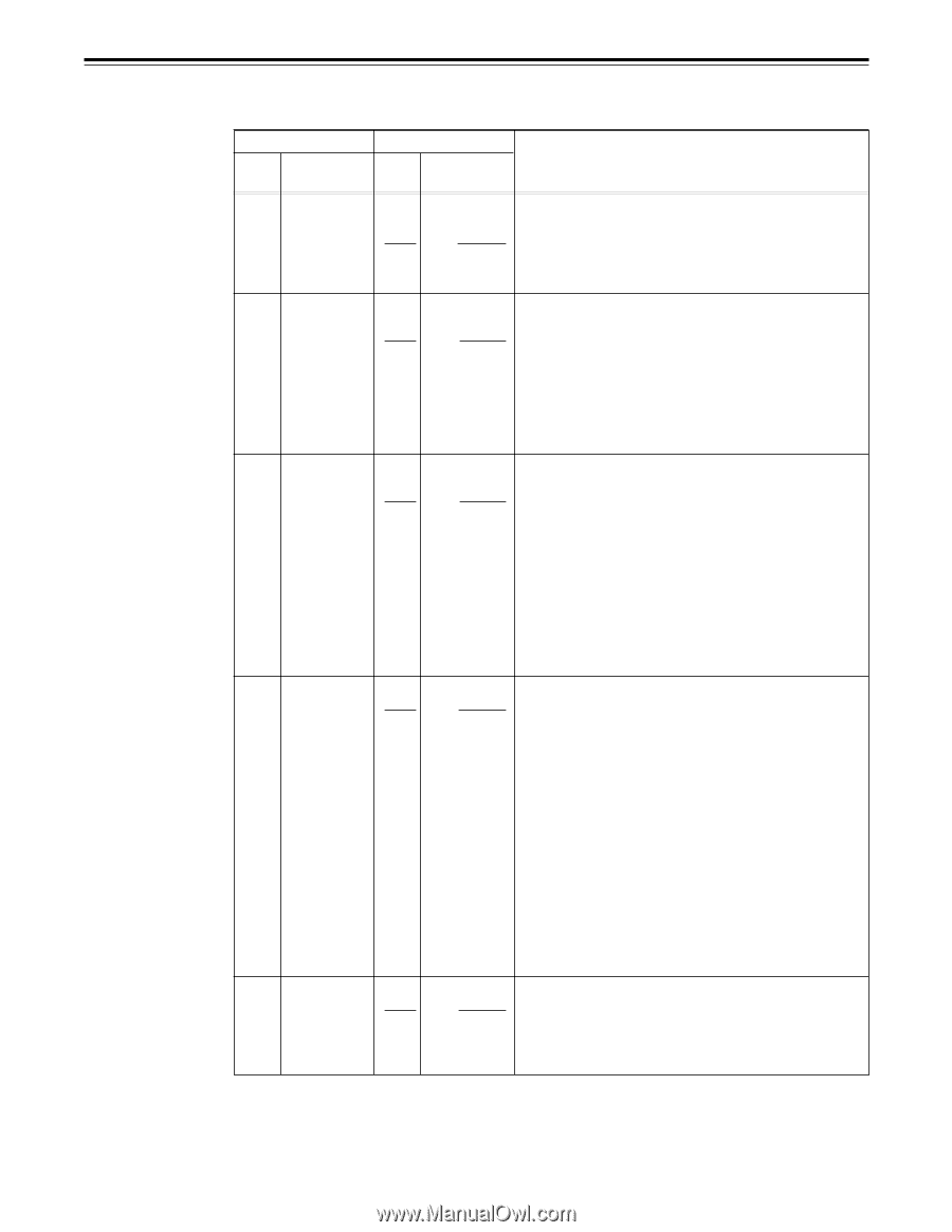
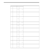
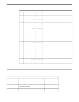
Setup menus USER menu Item Superimposed No. display Setting Superimposed No. display Description 000 P-ROLL TIME 000... 0 000... 5 0015 0...S 5...S 15S This sets the preroll time which can be set from 0 to 15 seconds in 1-second increments. The unit will not operate if the preroll time is set to 0 seconds when the unit is set to automatic editing (PREVIEW, AUTO EDIT COMMAND) from an external controller. 001 CHARA H-POS 000... 0 000... 4 0016 0... This sets the position of the characters on the horizontal plane for the time code and other super displays output to the 4... VIDEO OUT 3/SERIAL OUT 3* connector. 16 When setting this item, the DISPLAY SEL status is output to VIDEO OUT 3/SERIAL OUT 3* even if SUPER OFF has been set. However, when the menu is exited, operation complies with the SUPER OFF/ON setting. Also, CHARA TYPE is output to VIDEO OUT 3/SERIAL OUT 3* according to the status set in the menu. 002 CHARA V-POS 000... 0 001... 8 0022 0... This sets the position of the characters on the vertical plane for the time code and other super displays output to the 18... VIDEO OUT 3/SERIAL OUT 3* connector. 22 1. When setting this item, the DISPLAY SEL status is output to VIDEO OUT 3/SERIAL OUT 3* even if SUPER OFF has been set. However, when the menu is exited, operation complies with the SUPER OFF/ON setting. Also, CHARA TYPE is output to VIDEO OUT 3/SERIAL OUT 3* according to the status set in the menu. 2. When the DISPLAY SEL setting causes characters to extend beyond the edges of the screen, the setting value is changed so that the characters are automatically displayed in a position on the screen. 003 DISPLAY SEL 0000 0001 0002 0003 0004 0005 0006 TIME T&STA T&S&M T&RT T&YMD T&MDY T&DMY For selecting the time code and/or other information which is to be shown on the superimposed display at the VIDEO OUT 3/ SERIAL OUT 3* connector. 0: Time only 1: Time and operation mode 2: Time, operation mode and mode 3: Time and REC TIME 4: Time and REC DATE (year/month/day) 5: Time and REC DATE (month/day/year) 6: Time and REC DATE (day/month/year) 1. The mode display is DVCPRO during DVCPRO playback, DV during DV playback, and DVCAM during DVCAM playback. 2. When 2 (T&S&M) is set, an error message will appear when a warning or error has occurred. 3. REC TIME and REC DATE are displayed during DV or DVCAM playback only. The operation mode is displayed during DVCPRO playback. * The SERIAL OUT 3 connector functions only when the AJ-YA455P serial interface board (optional accessory) is used. 004 LOCAL ENA 0000 0001 0002 DIS ST&EJ ENA This selects the buttons which can be operated on the front panel when the REMOTE/LOCAL switch has been set to REMOTE. 0: No buttons can be operated. 1: Only the STOP and EJECT buttons can be operated. 2: All buttons can be operated. The underline on the setting item denotes the initial setting. 22
-
 1
1 -
2
-
3
-
4
-
5
-
6
-
7
-
8
-
9
-
10
-
11
-
12
-
13
-
14
-
15
-
16
-
 17
17 -
 18
18 -
 19
19 -
 20
20 -
 21
21 -
 22
22 -
 23
23 -
 24
24 -
 25
25 -
 26
26 -
 27
27 -
28
-
29
-
30
-
31
-
32
-
33
-
34
-
35
-
36
-
37
-
38
-
39
-
40
-
41
-
42
-
43
-
44
-
45
-
46
-
47
-
48
-
49
-
50
-
51
-
52
 |
 |