Panasonic AJD455 AJD455 User Guide - Page 7
EDIT/EDIT REC/REC/REC INH lamps, Tape counter type display
 |
View all Panasonic AJD455 manuals
Add to My Manuals
Save this manual to your list of manuals |
Page 7 highlights
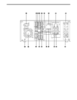
q POWER switch When the ON side is pressed, the power is switched on, and the counter display lights up. w Cassette insertion slot e EJECT button When this is pressed, the tape is unloaded and several seconds later the cassette is automatically ejected. When the counter display indicates "CTL", the display is reset. r EDIT/EDIT REC/REC/REC INH lamps EDIT: This lights when the editing mode is chosen from the 9P remote control. EDIT REC: This lights when editing from the 9P remote control. REC: This lights during video recording. REC INH: This lights when the accidental erasure prevention mode has been set for the cassette. In this state, neither recording nor editing is possible. t REMOTE lamp This lights when the REMOTE/LOCAL switch has been set to the REMOTE position. y WIDE lamp This lights when the unit is in 16:9 wide screen mode. u Tape counter type display CTL: This indicates the tape timer (control signal). TC: This indicates the time code. UB: This indicates the user bit. No lighting: The remaining tape is displayed. i SCH lamp This lights when the SCH phase of the reference video signal is within the prescribed range. o SERVO lamp This lights when the drum servo and capstan servo have locked. !0 Channel condition lamps One of these lamps lights in accordance with the error rate status. (Green→blue→red) Green: This lights when the error rates for the video and audio playback signals are both acceptable. Blue: This lights when the error rate for the video or audio playback signals has deteriorated. The playback picture will remain normal even when this lamp lights. Red: This lights when the video or audio signals are subject to rectification or interpolation. !1 Level meters These indicate the PCM audio signal CH1/CH2. The audio signal indicates the input signal levels during recording and EE selection, and the output signal levels during playback. !2 Cassette insertion display lamp This lights when a cassette has been inserted into the unit. !3 Counter display This displays the TC and CTL count values, on-screen information and other messages. 7
-
 1
1 -
 2
2 -
 3
3 -
 4
4 -
 5
5 -
 6
6 -
 7
7 -
 8
8 -
 9
9 -
 10
10 -
 11
11 -
 12
12 -
13
-
14
-
15
-
16
-
17
-
18
-
19
-
20
-
21
-
22
-
23
-
24
-
25
-
26
-
27
-
28
-
29
-
30
-
31
-
32
-
33
-
34
-
35
-
36
-
37
-
38
-
39
-
40
-
41
-
42
-
43
-
44
-
45
-
46
-
47
-
48
-
49
-
50
-
51
-
52
 |
 |
