Panasonic AJD455 AJD455 User Guide - Page 12
<Connector area>, ANALOG COMPOSITE VIDEO IN connectors and 75
 |
View all Panasonic AJD455 manuals
Add to My Manuals
Save this manual to your list of manuals |
Page 12 highlights
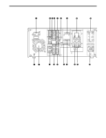
Controls and their functions q AC IN socket w SIGNAL GND terminal This is connected to the signal ground terminal on the component connected to the unit in order to reduce the noise. It is not a safety ground. e Fan motor This motor drives the fan to cool down the unit. r TIME CODE IN/OUT connectors These are the time code input and output connectors. t DIGITAL AUDIO IN/OUT connectors These are the input and output connectors for the digital audio signals complying with the AES/EBU standard. y ANALOG COMPONENT VIDEO IN connectors These are the analog component video signal input connectors. u ANALOG COMPOSITE VIDEO IN connectors and 75Ω termination switch These are the analog composite video signal input connectors. The two connectors are connected by a loop-through configuration. For termination, set the switch to ON. i REF VIDEO IN connectors and 75Ω termination switch These are the reference video signal input connectors. For termination, set the switch to ON. o REMOTE connector (RS-422A connector) The unit's operations can be controlled from an external component by connecting an external controller to the unit using this connector. !0 ANALOG AUDIO CH1/CH2 connectors These are the analog audio CH1 and CH2 input connectors. !1 S1-VIDEO IN/OUT connectors These are the S1-VIDEO signal input and output connectors. !2 ANALOG COMPONENT VIDEO OUT connectors These are the analog component video signal output connectors. !3 ANALOG COMPOSITE VIDEO OUT connectors These are the analog composite video signal output connector. Video signals with a superimposed display can be output from the VIDEO OUT 3 connector. Whether a display is to be superimposed onto the signals is selected using the SUPER ON/OFF switch. !4 RS-232C connector The unit's operations can be controlled by a personal computer or other component which is connected to the unit using this connector. !5 ENCODER REMOTE connector An external encoder controller is connected here to adjust the video output signal settings externally. 12
-
 1
1 -
2
-
3
-
4
-
5
-
6
-
 7
7 -
 8
8 -
 9
9 -
 10
10 -
 11
11 -
 12
12 -
 13
13 -
 14
14 -
 15
15 -
 16
16 -
 17
17 -
18
-
19
-
20
-
21
-
22
-
23
-
24
-
25
-
26
-
27
-
28
-
29
-
30
-
31
-
32
-
33
-
34
-
35
-
36
-
37
-
38
-
39
-
40
-
41
-
42
-
43
-
44
-
45
-
46
-
47
-
48
-
49
-
50
-
51
-
52
 |
 |
