Panasonic DMREZ17K Dvd Recorder - Page 51
DISC HANDLING, Opening the front panel
 |
View all Panasonic DMREZ17K manuals
Add to My Manuals
Save this manual to your list of manuals |
Page 51 highlights
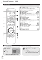
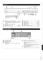
Main Unit 1 Disc tray The unit's display Remote control signal sensor Opening the front panel Press down on the part with your finger. 2 3 4 5 67 8 9 1 POWER on/off button (POWER ^/I 6) • Press to switch the unit from on to standby mode or vice versa. In the standby mode, the unit is still consuming a small amount of power. 2 Connector for a digital video (DV) camcorder 23) 3 IN2 input terminals (IN2 22) 4 Channel Select 6) 5 Stop button 6, 7) 6 Play/✕1.3 button 6) 7 Reset button 55) 8 Start recording 7) 9 Disc tray open/close button 6) The Unit's Display 1 2 54 1 Recording indicator 2 Main display section 3 Disc indicator This indicator lights up when a disc that is supported by this unit is inserted. 3 4 Scheduled recording indicator (➔ 8) On: When a scheduled recording program is registered and a recordable disc is inserted. Flashes: The scheduled recording indicator flashes when the unit cannot go to scheduled recording standby (e.g. there is no disc, etc). It does not flash if Quick Start is off. 5 Progressive indicator This indicator lights up when you select "On" in "Progressive" (➔ 31). Reference 51 RQT8850
-
 1
1 -
2
-
3
-
4
-
5
-
6
-
7
-
8
-
9
-
10
-
11
-
12
-
13
-
14
-
15
-
16
-
17
-
18
-
19
-
20
-
21
-
22
-
23
-
24
-
25
-
26
-
27
-
28
-
29
-
30
-
31
-
32
-
33
-
34
-
35
-
36
-
37
-
38
-
39
-
40
-
41
-
42
-
43
-
44
-
45
-
 46
46 -
 47
47 -
 48
48 -
 49
49 -
 50
50 -
 51
51 -
 52
52 -
 53
53 -
 54
54 -
 55
55 -
 56
56 -
57
-
58
-
59
-
60
-
61
-
62
-
63
-
64
-
65
-
66
-
67
-
68
-
69
-
70
-
71
-
72
 |
 |
