Panasonic NN-SE284 Installation Instructions - Page 10
Step 3: Installing The Mounting Bracket
 |
View all Panasonic NN-SE284 manuals
Add to My Manuals
Save this manual to your list of manuals |
Page 10 highlights
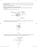
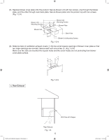
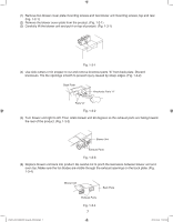
3. Fold the template along a "Rear wall" dotted line. Align the center line with center line on the wall and the top cabinet. Tape the template to the underneath of top cabinet and the wall. (Fig. 2-3) Template Taping Center Line Tape Center Line of Wall Fig. 2-3 3-1 Drill 3 pilot holes at the center point (No.q and No.w in Fig. 2-1) If Top Exhaust application is chosen, you will need 4 more pilot holes. (No.e in Fig. 2-1) If Rear Exhaust application is chosen, you will need 4 more pilot holes. (No.r in Fig. 2-1) 3-2 Remove the template. 3-3 Drill two 1/2" holes from the No.q pilot holes. Drill a 13/16" hole from the No.w pilot hole for AC cord. 3-4 If Top Exhaust application is chosen, you will need to cut the Top Exhaust opening. (No.t in Fig. 2-1) If Rear Exhaust application is chosen, you will need to cut the Rear Exhaust opening. (No.y in Fig. 2-1) STEP 3: INSTALLING THE MOUNTING BRACKET CAUTION: To support the oven's weight, bracket must be secured by at least • Four wood screws on the wall studs (2 screws on each side) or • Two wood screws on the wall studs and 4 toggle bolts through the wall PREPARATION OF BRACKET ASSEMBLY Note: If Rear Exhaust is chosen, the product need a Rear Wall Exhaust cutout opening for the Rear Wall duct and the Exhaust adaptor must be installed on the bracket (hardware item y) with two screws. (hardware item t) (Fig. 2-1). Check that the damper blade moves smoothly and opens fully as shown. (Fig. 3-1) Fig. 3-1 Damper Blade Opens Fully Exhaust Damper Mounting Screws IP3297_F03138Q03CP_Eng_00_101028.indd 10 10 2010-10-28 11:51:30
-
 1
1 -
2
-
3
-
4
-
 5
5 -
 6
6 -
 7
7 -
 8
8 -
 9
9 -
 10
10 -
 11
11 -
 12
12 -
 13
13 -
 14
14
 |
 |
