Panasonic NN-SE284 Installation Instructions - Page 3
B Installation Hardware, C Installation Procedure
 |
View all Panasonic NN-SE284 manuals
Add to My Manuals
Save this manual to your list of manuals |
Page 3 highlights
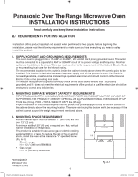
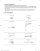
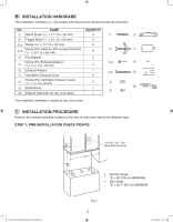
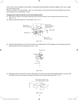
B INSTALLATION HARDWARE The installation hardware (q~a) packed with the products should include the following: NO. NAME QUANTITY q Wood Screw 5/32" × 13/4" (5 × 45 mm) 4 q y w Toggle Bolts 5/32" × 23/8" (5 × 60 mm) 4 e-a Screw 5/32" × 11/2" (5 × 40 mm) 2 Screw (For cabinets with recessed bottom) e-b 5/32" × 31/8" (5 × 80 mm) 2 w u r Flat Washer t Screw (For E×haust Adaptor) 5/32" × 3/8" (4 × 10 mm) 2 2 e-a i y Exhaust Adaptor u Ventilation Exhaust Cover 1 e-b o 2 i Screw (For Ventilation Exhaust Cover) 1/8" × 5/16" (3 × 8 mm) 2 r o Metal Brace 1 a t a Bracket Assembly (at rear of product) 1 The installation hardware is taped on top of the oven. C INSTALLATION PROCEDURE Remove the bracket assembly located on the rear of oven and remove all adhesive tape. STEP 1: PRE-INSTALLATION CHECK POINTS IP3297_F03138Q03CP_Eng_00_101028.indd 3 12" MIN *D 120V AC, min. 15A separated line outlet 30" • Electric range: *D = 30" (76 cm) MINIMUM • Gas range: *D = 323/8" (82 cm) MINIMUM Fig. 1 3 2010-10-28 11:51:29
-
 1
1 -
 2
2 -
 3
3 -
 4
4 -
 5
5 -
 6
6 -
 7
7 -
 8
8 -
 9
9 -
10
-
11
-
12
-
13
-
14
 |
 |
