Panasonic PT-50LC13 Multi-media Display - Page 11
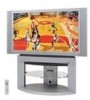
Model PT-50LC13 unit shown, VHF/UHF, terminal, PP. 12-14
 |
UPC - 037988974924
View all Panasonic PT-50LC13 manuals
Add to My Manuals
Save this manual to your list of manuals |
Page 11 highlights
Getting Started Model PT-50LC13 unit shown < REAR > Location of Controls < SIDE > Vent Vent VHF/UHF terminal (PP. 12-14) RGB Input 1 terminal (PP. 18-19) Digital Input terminal (P. 20) RGB Input 2 terminal (PP. 18-19) Input 1, 2 terminals (P. 15) Component signal input 1-4 terminals (P. 16) AV out terminals (P. 17) Input 3 terminals (P. 15) Note: Make sure the vents are not blocked. (This could cause damage.) 11
-
 1
1 -
2
-
3
-
4
-
5
-
 6
6 -
 7
7 -
 8
8 -
 9
9 -
 10
10 -
 11
11 -
 12
12 -
 13
13 -
 14
14 -
 15
15 -
 16
16 -
17
-
18
-
19
-
20
-
21
-
22
-
23
-
24
-
25
-
26
-
27
-
28
-
29
-
30
-
31
-
32
-
33
-
34
-
35
-
36
-
37
-
38
-
39
-
40
-
41
-
42
-
43
-
44
-
45
-
46
-
47
-
48
-
49
-
50
-
51
-
52
-
53
-
54
-
55
-
56
-
57
-
58
-
59
-
60
-
61
-
62
-
63
-
64
-
65
-
66
-
67
-
68
-
69
-
70
-
71
-
72
-
73
-
74
-
75
-
76
-
77
-
78
-
79
-
80
 |
 |

11
Getting Started
< REAR >
VHF/UHF
terminal
(PP. 12-14)
Vent
Note:
Make sure the vents are not blocked. (This could cause damage.)
Location of Controls
Vent
Component signal input 1-4 terminals
(P. 16)
AV out terminals
(P. 17)
Input 1, 2 terminals
(P. 15)
RGB Input 1 terminal
(PP. 18-19)
Digital Input terminal
(P. 20)
< SIDE >
Input 3 terminals
(P. 15)
RGB Input 2 terminal
(PP. 18-19)
Model PT-50LC13 unit shown