Panasonic PT-50LC13 Multi-media Display - Page 18
How to connect the RGB IN Terminals, RGB IN Terminal D-SUB 15P Pin Layouts, Connecting a PC to RGB - model
 |
UPC - 037988974924
View all Panasonic PT-50LC13 manuals
Add to My Manuals
Save this manual to your list of manuals |
Page 18 highlights
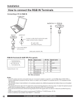
Installation How to connect the RGB IN Terminals Connecting a PC to RGB IN COMPUTER RGB OUT AUDIO OUT Connect a cable which matches the audio output terminal on the computer. PC audio cable (M3 stereo mini pin) Conversion adapter (If necessary) RGB cable (D-SUB 15P) RGB IN Terminal (D-SUB 15P) Pin Layouts 11 12 13 14 15 6 7 8 9 10 12345 Connection port view Pin No. Signal name 1R 2G 3B 4 NC 5 NC 6 Ground for R 7 Ground for G 8 Ground for B NC: Not connected Pin No. Signal name 9 NC 10 Ground 11 NC 12 NC 13 HD/CSYNC 14 VD 15 NC Notes: • Some PC models cannot be connected to the set. A conversion adapter is required to use the RGB cable (D-SUB 15P) to connect a Macintosh computer to the set. There is no need to use an adapter for computers with PC / AT compatible D-SUB 15P terminal. • The computer shown in the illustration is for example purposes only. Additional equipment and cables shown are not supplied with this set. • The picture will become dark if an PC signal with a vertical scanning frequency of 62 Hz is input. To obtain the optimum picture quality with the projection display, a vertical scanning frequency of 60 Hz is recommended. • Do not set the horizontal and vertical scanning frequencies for PC signals which are above or below the specified frequency range. • Select the desired RGB input position by pressing the PC/MENU or TV/VIDEO button. (P. 35) • Similar connections are available at the RGB IN 1, 2 Terminals. 18 For assistance, please call : 1-888-VIEW PTV(843-9788)
-
 1
1 -
2
-
3
-
4
-
5
-
6
-
7
-
8
-
9
-
10
-
11
-
12
-
 13
13 -
 14
14 -
 15
15 -
 16
16 -
 17
17 -
 18
18 -
 19
19 -
 20
20 -
 21
21 -
 22
22 -
 23
23 -
24
-
25
-
26
-
27
-
28
-
29
-
30
-
31
-
32
-
33
-
34
-
35
-
36
-
37
-
38
-
39
-
40
-
41
-
42
-
43
-
44
-
45
-
46
-
47
-
48
-
49
-
50
-
51
-
52
-
53
-
54
-
55
-
56
-
57
-
58
-
59
-
60
-
61
-
62
-
63
-
64
-
65
-
66
-
67
-
68
-
69
-
70
-
71
-
72
-
73
-
74
-
75
-
76
-
77
-
78
-
79
-
80
 |
 |
