Panasonic PT-50LC13 Multi-media Display - Page 20
How to connect the DIGITAL IN Terminal, DIGITAL IN Terminal Pin Layouts
 |
UPC - 037988974924
View all Panasonic PT-50LC13 manuals
Add to My Manuals
Save this manual to your list of manuals |
Page 20 highlights
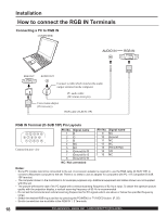
Installation How to connect the DIGITAL IN Terminal The video signal is digitally input to the projection display for superior picture quality enjoyment. Connecting a DTV Decoder to DIGITAL IN DTV Decoder AUDIO OUT AUDIO DVI cable By inputting a High-bandwidth Digital Content Protection high-definition picture source to the DIGITAL IN terminal of this projection display, high-definition pictures can be displayed on the screen in their digital form. (This terminal is for use in the future when High-bandwidth Digital Content Protection DTV decoders, DVD players and D-VHS are put on the market.) Notes: • Select the DIGITAL input position by pressing the TV/VIDEO button. (P. 35) • The DIGITAL IN terminal can only be used with 1080i, 720p and 480p picture signals. Set the DTV Decoder DIGITAL OUT terminal to 1080i, 720p, or 480p signal output. Please refer to the DTV Decoder instruction manual. • If no picture is displayed because the DTV Decoder output cannot be set, use the component Video Input, S-Video Input, or Video Input. This will display the picture as an analog signal. DIGITAL IN Terminal Pin Layouts 24 17 9 16 8 1 Connection port view Pin No. Signal name 1 T.M.D.S Data 22 T.M.D.S Data 2+ 3 T.M.D.S Data 2 Shield 4 NC 5 NC 6 DDC Clock 7 DDC Data 8 NC 9 T.M.D.S Data 110 T.M.D.S Data 1+ 11 T.M.D.S Data 1 Shield 12 NC NC: Not connected Pin No. Signal name 13 NC 14 +5 V 15 GND 16 Hot Plug Detect 17 T.M.D.S Data 018 T.M.D.S Data 0+ 19 T.M.D.S Data 0 Shield 20 NC 21 NC 22 T.M.D.S Clock Shield 23 T.M.D.S Clock + 24 T.M.D.S Clock - 20 For assistance, please call : 1-888-VIEW PTV(843-9788)
-
 1
1 -
2
-
3
-
4
-
5
-
6
-
7
-
8
-
9
-
10
-
11
-
12
-
13
-
14
-
 15
15 -
 16
16 -
 17
17 -
 18
18 -
 19
19 -
 20
20 -
 21
21 -
 22
22 -
 23
23 -
 24
24 -
 25
25 -
26
-
27
-
28
-
29
-
30
-
31
-
32
-
33
-
34
-
35
-
36
-
37
-
38
-
39
-
40
-
41
-
42
-
43
-
44
-
45
-
46
-
47
-
48
-
49
-
50
-
51
-
52
-
53
-
54
-
55
-
56
-
57
-
58
-
59
-
60
-
61
-
62
-
63
-
64
-
65
-
66
-
67
-
68
-
69
-
70
-
71
-
72
-
73
-
74
-
75
-
76
-
77
-
78
-
79
-
80
 |
 |
