Panasonic PT-DW5000U Dlp Projector- English/french - Page 11
Front And Side Of The Projector, Lamp1 Monitor
 |
UPC - 791871111338
View all Panasonic PT-DW5000U manuals
Add to My Manuals
Save this manual to your list of manuals |
Page 11 highlights
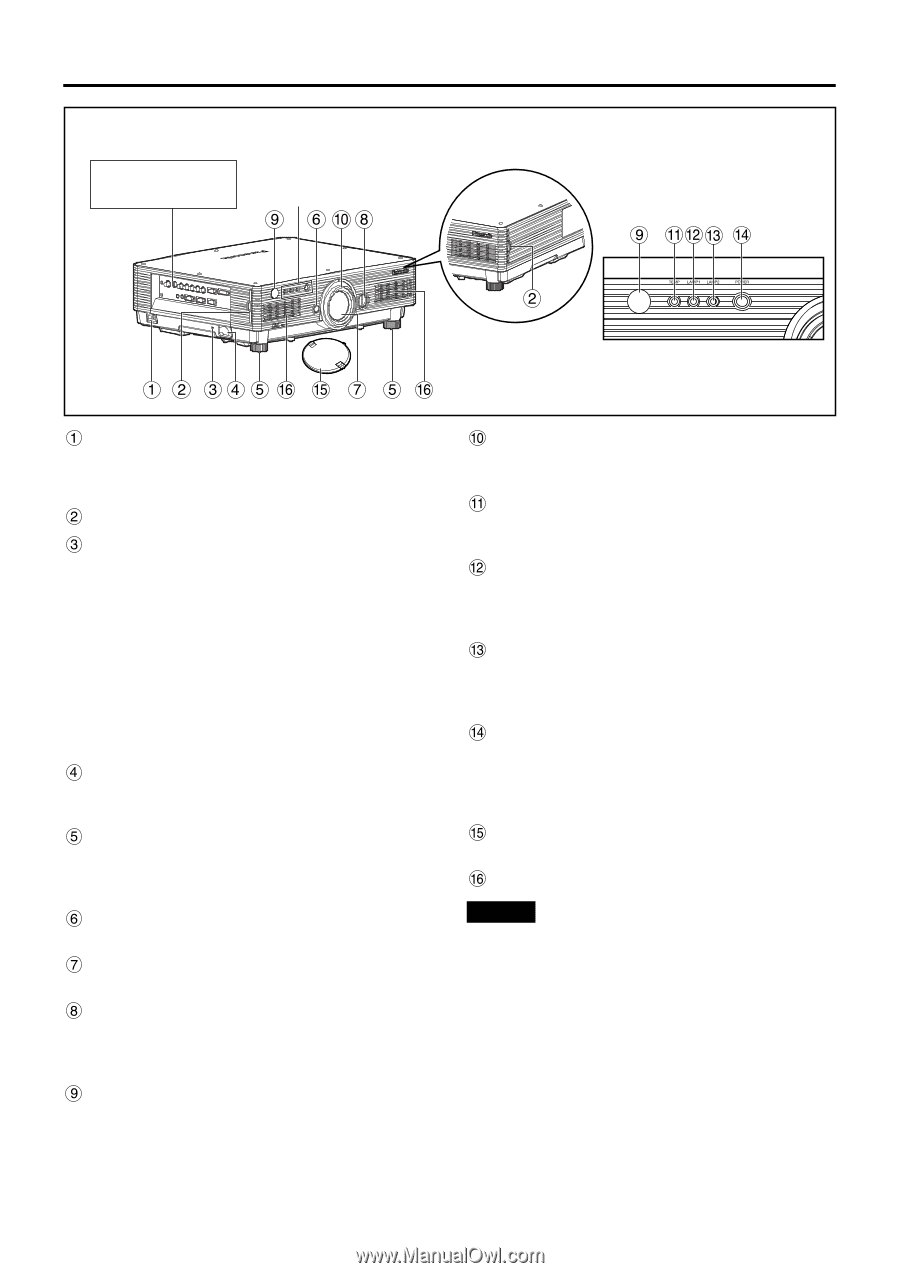
Front and side of the projector Side-mounted connection terminals (page 13) Status LED lights (Refer to the figure on the right.) Status LED lights AC IN terminal (page 23) Connect the supplied line power cord into this receptacle. Do not connect any other cable to this socket. Air filter (page 42) Burglar lock Attach a commercial burglar prevention cable (e.g., from Kensington) to this lock port. It is compatible with the Microsaver Security System from Kensington. Contact details for this company are given below. Kensington Technology Group ACCO Brands Inc. 2885 Campus Drive San Mateo, CA94403 Tel (650)572-2700 Fax (650)572-9675 http://www.kensington.com/ http://www.gravis.com/ Clasp for attaching anti-theft chain Attach a chain or other fastening device available from a hardware store through this clamp. Level-adjusting feet (page 23) Use these feet to adjust the tilt of the projector. (The leveling feet at the front left and right can be adjusted.) Lens lock button (page 25) Press this to remove the projection lens. Projection lens Lens for projecting images on the screen. Lens left/right adjusting dial (page 25) Turn this clockwise to move the screen to the left; conversely, turn it counterclockwise to move it to the right. Remote control receiver window (front) (page 14) This window receives the signal beam emitted from the remote control. Focus ring (page 25) For focus adjustment. Powered focus adjustment is also available. Temperature monitor (TEMP) (page 41) Lighting or blinking of this lamp indicates an abnormal condition of the internal temperature. LAMP1 monitor (page 41) This lamp lights up when the time to replace lamp unit 1 is reached. It also blinks if something unusual occurs in the lamp circuit. LAMP2 monitor (page 41) This lamp lights up when the time to replace lamp unit 2 is reached. It also blinks if something unusual occurs in the lamp circuit. Power indicator (page 23) The lamp lights in red when the MAIN POWER switch is turned to " | " (on). It turns to green when the POWER ON button of the remote control or the main unit is pressed. Lens cap Cap the lens whenever the projector is left unused. Ventilation holes Attention • Do not remove the upper cover (white top panel). 11
-
 1
1 -
2
-
3
-
4
-
5
-
 6
6 -
 7
7 -
 8
8 -
 9
9 -
 10
10 -
 11
11 -
 12
12 -
 13
13 -
 14
14 -
 15
15 -
 16
16 -
17
-
18
-
19
-
20
-
21
-
22
-
23
-
24
-
25
-
26
-
27
-
28
-
29
-
30
-
31
-
32
-
33
-
34
-
35
-
36
-
37
-
38
-
39
-
40
-
41
-
42
-
43
-
44
-
45
-
46
-
47
-
48
-
49
-
50
-
51
-
52
-
53
-
54
-
55
-
56
-
57
-
58
-
59
-
60
-
61
-
62
-
63
-
64
-
65
-
66
-
67
-
68
 |
 |