Panasonic TH-103PB1U Operating Instructions - Page 53
Adjustments
 |
View all Panasonic TH-103PB1U manuals
Add to My Manuals
Save this manual to your list of manuals |
Page 53 highlights
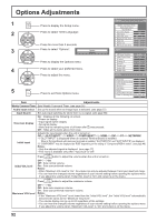
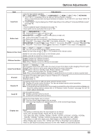
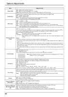
Options Adjustments Item Input lock Button lock Adjustments Locks the input switch operation. Off SLOT INPUT*1 VIDEO COMPONENT*2 HDMI DVI PC *1 "SLOT INPUT" is displayed when an optional Terminal Board is installed. NETWORK When a Terminal Board with dual input terminals is installed, "SLOT INPUT A" and "SLOT INPUT B" are displayed. *2 "COMPONENT" may be displayed as "RGB" depending on the setting of "Component/RGB-in select". (see page 48) Notes: • Only the adjusted signal is displayed (see page 17). • Input switch can be used when this is set to "Off". Off MENU&ENTER On Off: All the buttons on main unit can be used. MENU&ENTER: Locks MENU and ENTER/ buttons on main unit. On: Locks all the button on main unit. Sets Button lock with the unit buttons in the following procedure. Off: Press + / four timesĺPress INPUT four timesĺPress - / four timesĺPress ENTER/ MENU&ENTER: Press ENTER/ four timesĺPress + / four timesĺPress INPUT four timesĺPress ENTER/ On: Press - / four timesĺPress ENTER/ four timesĺPress + / four timesĺPress ENTER/ Remocon User level Off User1 User2 User3 Off: You can use all of the buttons on the remote control. User1:You can only use , , , , buttons on the remote control. User2:You can only use button on the remote control. User3:Locks all the buttons on remote control. Off-timer function Enable: Enables the "Off-timer function". Disable:Disables the "Off-timer function". Note: When "Disable" is set, the Off-timer is cancelled. Initial Power Mode ID select Remote ID Serial ID Normal Standby On Sets the power mode of the unit for when the power recovers from failure or after plugging off and in again. Normal: Power returns in as the same state as before the power interruption. Standby:Power returns in standby mode. (Power Indicator : red/orange) On: Power returns in power On. (Power Indicator : green) Note: When using multiple displays, "Standby" is preferred to be set in order to reduce a power load. Sets panel ID number when panel is used in "Remote ID" or "Serial ID". Set value range: 0 - 100 (Standard value: 0) The setting of this menu is valid only when using ID remote control. Off: Disables ID remote control functions. You can use normal remote control operations. On: Enable ID remote control functions. Note: To use the ID remote control function, it is necessary to set each ID number of remote control and display unit. About the setting method, please refer to "ID Remote Control Function" (see page 45) and "ID select" (above-mentioned). Sets the panel ID Control. Off: Disables external control by the ID. On: Enables the external control by the ID. Adjusts the image display size on screen. Off: Sets the normal image display size on screen. On: Sets the image display size approximately 95 % of the normal image display. Off On Display size Notes: • This setting is valid only when the input signals are as follows; NTSC, PAL, SECAM, M.NTSC, PAL60, PAL-M, PAL-N (Video) 525i, 525p, 625i, 625p, 750/60p, 750/50p, 1125/60i, 1125/50i, 1125/24sF, 1125/25p, 1125/24p, 1125/30p, 1125/60p, 1125/50p, 1250/50i (Component Video, RGB, DVI, SDI, HDMI) • This setting is invalid when digital zoom, Multi display or Portrait display is selected. • When "Display size" is set to "On", "H-Pos" and "V-Pos" in "Pos./Size" can be adjusted. • Refer to each board's operating instruction for DVI, SDI, HDMI's corresponding signals. 53
-
 1
1 -
2
-
3
-
4
-
5
-
6
-
7
-
8
-
9
-
10
-
11
-
12
-
13
-
14
-
15
-
16
-
17
-
18
-
19
-
20
-
21
-
22
-
23
-
24
-
25
-
26
-
27
-
28
-
29
-
30
-
31
-
32
-
33
-
34
-
35
-
36
-
37
-
38
-
39
-
40
-
41
-
42
-
43
-
44
-
45
-
46
-
47
-
 48
48 -
 49
49 -
 50
50 -
 51
51 -
 52
52 -
 53
53 -
 54
54 -
 55
55 -
 56
56 -
 57
57 -
 58
58 -
59
-
60
-
61
-
62
-
63
-
64
-
65
 |
 |
