Pioneer 614MX Operating Instructions - Page 13
SOUND Settings Menu, SCREEN Settings Menu, Option1 Settings Menu
 |
UPC - 012562732336
View all Pioneer 614MX manuals
Add to My Manuals
Save this manual to your list of manuals |
Page 13 highlights
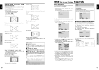
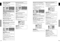
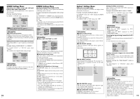
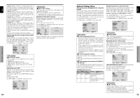
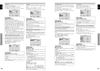
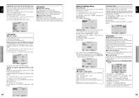
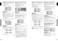
English OSD (On Screen Display) Controls SOUND Settings Menu Adjusting the treble, bass and left/right balance and audio input select The treble, bass and left/right balance can be adjusted to suit your tastes. Example: Adjusting the bass On "BASS" of "SOUND" menu, adjust the bass. BASS TREBLE BALANCE AUDIO INPUT1 AUDIO INPUT2 AUDIO INPUT3 SOUND : VIDEO1 : COMPNT1 : PC1DSUB SEL. ADJ. EXIT RETURN Note : If "CAN NOT ADJUST" appears... Set "AUDIO INPUT" on the SOUND menu correctly. Information Ⅵ SOUND settings menu BASS: Controls the level of low frequency sound. TREBLE: Controls the level of high frequency sound. BALANCE: Controls the balance of the left and right channels. Setting the allocation of the audio connectors Setting the AUDIO 1, 2, and 3 connectors to the desired input. Example: Setting "AUDIO INPUT1" to "VIDEO 2" On "AUDIO INPUT1" of "SOUND" menu, select "VIDEO2". The available sources depend on the settings of input. BASS TREBLE BALANCE AUDIO INPUT1 AUDIO INPUT2 AUDIO INPUT3 SOUND : VIDEO2 : COMPNT1 : PC1DSUB SEL. ADJ. EXIT RETURN Information Ⅵ AUDIO INPUT A single audio input cannot be selected as the audio channel for more than one input terminal. SCREEN Settings Menu Adjusting the Position, Size, PHASE, CLOCK The position of the image can be adjusted and flickering of the image can be corrected. Example: Adjusting the vertical position in the normal mode On "V.POSITION" of "SCREEN" menu, adjust the position. The mode switches as follows each time the ᮤ or ᮣ button is pressed: 4:3 C FULL * The mode can also be switched by pressing the SCREEN SIZE button on the remote control. * The settings on the SCREEN menu are not preset at the factory. SCREEN SCREEN SIZE : 4:3 V. POSITION H. POSITION V. SIZE H. SIZE AUTO PICTURE : OFF PHASE CLOCK V.POSITION +64 SEL. ADJ. EXIT RETURN Information Ⅵ When "AUTO PICTURE" is "OFF" SCREEN SCREEN SIZE : FULL V. POSITION H. POSITION V. SIZE H. SIZE AUTO PICTURE : OFF PHASE CLOCK SEL. ADJ. EXIT RETURN When Auto Picture is off, the PHASE and the CLOCK items are displayed so that you can adjust them. Ⅵ Adjusting the Auto Picture ON: The CLOCK, PHASE and Position adjustments are made automatically. Not available for digital ZOOM. OFF: The CLOCK, PHASE and Position adjustments are made manually. * If PHASE can't be adjusted, set Auto Picture to OFF and adjust manually. Ⅵ Adjusting the position of the image V.POSITION: Adjusts the vertical position of the image. H.POSITION: Adjusts the horizontal position of the image. V.SIZE: Adjusts the vertical size of the image. (Except for WIDE mode) H.SIZE: Adjusts the horizontal size of the image. (Except for WIDE mode) PHASE*: Adjusts for flickering. CLOCK*: Adjusts for striped patterns on the image. * The CLOCK and PHASE features are available only when the "Auto Picture" is off. * The AUTO PICTURE, PHASE and CLOCK are available only for RGB signals. But, these features are not available for moving pictures on RGB, VIDEO or COMPONENT. 16 En Option1 Settings Menu Setting the on-screen display This sets the position of the menu, the display format (horizontal or vertical) etc. Example: Turning the DISPLAY OSD off On "OPTION1" menu, select "OSD", then press the MENU/ SET button. The "OSD" menu appears. On "DISPLAY OSD" of "OSD" menu, select "OFF". DISPLAY OSD OSD ADJUST OSD ANGLE OSD ORBITER OSD CONTRAST OSD : OFF : 1 : H : OFF : LOW SEL. ADJ. EXIT RETURN Information Ⅵ DISPLAY OSD settings ON: The informations on screen size, volume control, etc. will be shown. OFF: The informations on screen size, volume control, etc. will not be shown. The DISPLAY button on the remote control will not function either. Ⅵ OSD ADJUST settings Adjusts the position of the menu when it appears on the screen. The position can be set between 1 to 6. Ⅵ OSD ANGLE settings Sets the display format (landscape "H" or portrait "V"). When the unit is installed vertically set the OSD ANGLE at "V". "H" "V" OPTION1 1 / 3 OSD BNC INPUT : RGB D-SUB INPUT : RGB RGB SELECT : AUTO HD SELECT : 1080B INPUT SKIP : OFF ALL RESET : OFF NEXT PAGE SEL. MENU OK EXIT RETURN OSD OPTION1 BNC INPUT : RGB D-SUB INPUT : RGB RGB SELECT : AUTO HD SELECT : 1080B INPUT SKIP : OFF ALL RESET : OFF 1024768 SEL. MENU OK EXIT RETURN Ⅵ OSD ORBITER settings ON: The position of the menu will be shifted by eight dots each time OSD is displayed. OFF: OSD will be displayed at the same position. Ⅵ OSD CONTRAST settings NORMAL: OSD brightness is set to normal. LOW: OSD brightness is set to lower. Setting the BNC connectors Select whether to set the input of the 5 BNC connectors to RGB and component. Example: Set the BNC INPUT mode to "COMP." On "BNC INPUT" of "OPTION1" menu, select "COMP.". OPTION1 1 / 3 OSD BNC INPUT : COMP. D-SUB INPUT : RGB RGB SELECT : AUTO HD SELECT : 1080B INPUT SKIP : OFF ALL RESET : OFF NEXT PAGE SEL. ADJ. EXIT RETURN Information Ⅵ BNC INPUT Settings RGB: Use the 5BNC terminals for PC2/ COMPONENT2 input. COMP.: Use the 3BNC terminals for PC2/ COMPONENT2 input. Checking the signal being transmitted to PC1 terminal Use this to confirm the signal being transmitted to the PC1 terminal. It is set to RGB and can not be adjusted. OPTION1 1 / 3 OSD BNC INPUT : RGB D-SUB INPUT : RGB RGB SELECT : AUTO HD SELECT : 1080B INPUT SKIP : OFF ALL RESET : OFF NEXT PAGE CAN NOT ADJUST Setting a computer image to the correct RGB select screen With the computer image, select the RGB Select mode for a moving image such as (video) mode, wide mode or digital broadcast. Example: Setting the "RGB SELECT" mode to "MOTION " On "RGB SELECT" of "OPTION1" menu, select "MOTION". OPTION1 1 / 3 OSD BNC INPUT : RGB D-SUB INPUT : RGB RGB SELECT HD SELECT : MOTION : 1024×768 INPUT SKIP : OFF ALL RESET : OFF NEXT PAGE SEL. ADJ. EXIT RETURN Information Ⅵ RGB SELECT modes One of these 8 modes must be selected in order to display the following signals correctly. AUTO: Select the suitable mode for the specifications of input signals as listed in the table "Computer input signals supported by this system" on page 30. STILL: To display VESA standard signals. (Use this mode for a still image from a computer.) MOTION: The video signal (from a scan converter) will be converted to RGB signals to make the picture more easily viewable. (Use this mode for a motion image from a computer.) OSD (On Screen Display) Controls English 17 En
-
 1
1 -
2
-
3
-
4
-
5
-
6
-
7
-
 8
8 -
 9
9 -
 10
10 -
 11
11 -
 12
12 -
 13
13 -
 14
14 -
 15
15 -
 16
16 -
 17
17 -
 18
18 -
19
-
20
-
21
 |
 |