Pioneer 614MX Operating Instructions - Page 17
Video Wall setting
 |
UPC - 012562732336
View all Pioneer 614MX manuals
Add to My Manuals
Save this manual to your list of manuals |
Page 17 highlights
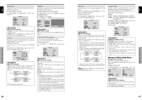
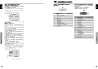
English Setting the power on mode This function sets the input mode at the time the power is switched on. Example: Setting "VIDEO2" Set "ADVANCED OSD" to "ON" in the main menu (1/ 2), then perform the following operations. On "PWR. ON MODE" of "OPTION3" menu, select "VIDEO2". The available inputs depend on the setting of input. OPTION3 3 / 3 PREVIOUS PAGE TIMER PWR. ON MODE : VIDEO2 KEY LOCK : OFF IR REMOTE : ON LOOP OUT : OFF ID NUMBER : ALL VIDEO WALL SEL. ADJ. EXIT RETURN Information Ⅵ PWR. ON MODE settings LAST: Last mode (the input that was last selected at the time the power was switched off). VIDEO1, 2, 3: VIDEO input mode. PC1, 2, 3: PC input mode. COMPONENT1, 2: COMPONENT input mode. Follow the procedure used for PROGRAM TIMER. See page 23. Enabling/disabling the front panel controls This function enables/disables the front panel controls. Example: Setting "ON" Set "ADVANCED OSD" to "ON" in the main menu (1/ 2), then perform the following operations. On "KEY LOCK" of "OPTION3" menu, select "ON", then press the MENU/SET button. OPTION3 3 / 3 PREVIOUS PAGE TIMER PWR. ON MODE : LAST KEY LOCK : ON IR REMOTE : ON LOOP OUT : OFF ID NUMBER : ALL VIDEO WALL SEL. ADJ. EXIT RETURN Information Ⅵ KEY LOCK settings ON: Disables the buttons on the front panel. OFF: Enables the buttons on the front panel. * Even when the KEY LOCK is set, the POWER switch will not be locked. * This becomes effective when the OSD goes out. Enabling/disabling remote control wireless transmission This function enables/disables remote control wireless transmission. Example: Setting "OFF" Set "ADVANCED OSD" to "ON" in the main menu (1/ 2), then perform the following operations. On "IR REMOTE" of "OPTION3" menu, select "OFF", then press the MENU/SET button. OPTION3 3 / 3 PREVIOUS PAGE TIMER PWR. ON MODE : LAST KEY LOCK : OFF IR REMOTE : OFF LOOP OUT : OFF ID NUMBER : ALL VIDEO WALL SEL. ADJ. EXIT RETURN Information Ⅵ IR REMOTE settings ON: Enables remote control wireless transmission. OFF: Disables remote control wireless transmission. Set "OFF" to avoid unwanted control from other remote controls. Loop Out setting When this feature is set to ON, the received signal will be looped out. Example: Setting "ON" Set "ADVANCED OSD" to "ON" in the main menu (1/ 2), then perform the following operations. On "LOOP OUT" of "OPTION3" menu, select "ON". OPTION3 3 / 3 PREVIOUS PAGE TIMER PWR. ON MODE : LAST KEY LOCK : OFF IR REMOTE : ON LOOP OUT : ON ID NUMBER : ALL VIDEO WALL SEL. ADJ. EXIT RETURN Information Ⅵ LOOP OUT settings ON: The received signal will be looped out via PC1 terminal or VIDEO1 terminal. OFF: The received signal will not loop out. * Even if LOOP OUT is ON, signals won't be sent out if POWER is being turned off. Ⅵ To connect another display... See page 3. Ⅵ If the PC1 signal is present at the time the power switched on... The PC1 input will be displayed regardless of the setting of LOOP OUT. OSD (On Screen Display) Controls 24 En English ID number setting When using more than one of these displays, this function sets ID numbers so that operation of the remote control does not cause multiple monitors to operate at the same time. Example: Setting "2" Set "ADVANCED OSD" to "ON" in the main menu (1/ 2), then perform the following operations. On "ID NUMBER" of "OPTION3" menu, select "2". OPTION3 3 / 3 PREVIOUS PAGE TIMER PWR. ON MODE : LAST KEY LOCK : OFF IR REMOTE : ON LOOP OUT : OFF ID NUMBER : 2 VIDEO WALL SEL. ADJ. EXIT RETURN * To reset back to ALL Press the CLEAR button. Information Ⅵ ID NUMBER settings ALL: ID NUMBER will not be set. 1 to 256: ID NUMBER will be set. Ⅵ When the ID NUMBER have been set You can also set ID NUMBER for each remote control to operate the plasma display individually. To do so, see below. To set the ID number for the remote control Example: Setting "2" Press the ID NO. SET button on the remote control. The "ID NO. SET" screen appears. On "ID NUMBER" of "ID NO. SET" menu, select "2". ID NO.SET POSITION : 1 ID NUMBER : 2 Note: A contingency method of shutting off the electric power should be used in cases of emergency during video wall setup. DIVIDER Set the 4-25 video wall. Example: Setting "4" On "DIVIDER" of "VIDEO WALL" menu, select "4". VIDEO WALL DIVIDER : 4 POSITION DISP. MODE : NORMAL AUTO ID : OFF SCREEN P. ON DELAY : OFF ABL LINK : OFF REPEAT TIMER : OFF SEL. ADJ. EXIT RETURN Information Ⅵ DIVIDER settings OFF, 1: 1 Screen (Matrix display function does not work) 4: 4 Screens (2×2 video wall) 9: 9 Screens (3×3 video wall) 16: 16 Screens (4×4 video wall) 25: 25 Screens (5×5 video wall) * When you select 4-25, set the VIDEO WALL POSITION. VIDEO WALL POSITION Set the position of each display. Example: Setting "4" On "VIDEO WALL" menu, select "POSITION", then press the MENU/SET button. The "VIDEO WALL POSITION" screen appears. Select "NO. 4" of "POSITION NO.". VIDEO WALL POSITION POSITION NO. 4 OSD (On Screen Display) Controls ADJ. EXIT RETURN * To reset back to ALL Press the CLEAR button. Video Wall setting When creating a video wall, use a distribution amplifier (any commercially available distribution amplifier) to connect the split signals to the respective monitor INPUT terminals. Use this feature to configure a 4-25 video wall. Set "ADVANCED OSD" to "ON" in the main menu (1/ 2), then perform the following operations. On "OPTION3" menu, select "VIDEO WALL", then press the MENU/SET button. The "VIDEO WALL" screen appears. VIDEO WALL DIVIDER : 1 POSITION DISP. MODE : NORMAL AUTO ID : OFF SCREEN P. ON DELAY : OFF ABL LINK : OFF REPEAT TIMER : OFF SEL. ADJ. EXIT RETURN ADJ. EXIT RETURN Information Ⅵ VIDEO WALL POSITION settings 1 Screen: There is no need to set POSITION. 4 Screens 9 Screens NO. 1 NO. 4 NO. 2 NO. 3 NO. 7 NO. 8 NO. 9 NO. 10 NO. 11 NO. 12 NO. 13 NO. 14 NO. 15 16 Screens NO. 16 NO. 17 NO. 18 NO. 19 NO. 20 NO. 21 NO. 22 NO. 23 NO. 24 NO. 25 NO. 26 NO. 27 NO. 28 NO. 29 NO. 30 NO. 31 25 Screens NO. 32 NO. 33 NO. 34 NO. 35 NO. 36 NO. 37 NO. 38 NO. 39 NO. 40 NO. 41 NO. 42 NO. 43 NO. 44 NO. 45 NO.46 NO. 47 NO. 48 NO. 49 NO. 50 NO. 51 NO. 52 NO. 53 NO. 54 NO. 55 NO. 56 25 En
-
 1
1 -
2
-
3
-
4
-
5
-
6
-
7
-
8
-
9
-
10
-
11
-
 12
12 -
 13
13 -
 14
14 -
 15
15 -
 16
16 -
 17
17 -
 18
18 -
 19
19 -
 20
20 -
 21
21
 |
 |