Pioneer 614MX Operating Instructions - Page 19
Pin Assignments
 |
UPC - 012562732336
View all Pioneer 614MX manuals
Add to My Manuals
Save this manual to your list of manuals |
Page 19 highlights
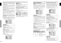
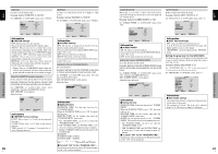
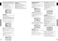
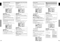
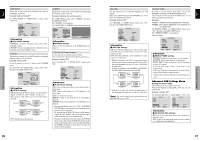
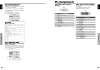
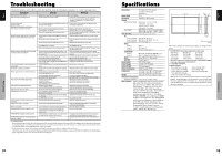
English Color System Settings Menu Setting the video signal format Use these operations to set the color systems of composite video signals or Y/C input signals. Example: Setting the color system to "3.58 NTSC" On the MAIN MENU, select "COLOR SYSTEM", then press the MENU/SET button. The "COLOR SYSTEM" screen appears. On "COLOR SYSTEM", select " 3.58NTSC ". COLOR SYSTEM COLOR SYSTEM : 3.58NTSC ADJ. EXIT RETURN Information Ⅵ Video signal formats Different countries use different formats for video signals. Set to the color system used in your current country. AUTO: The color systems are automatically identified and the format is set accordingly. PAL: This is the standard format used mainly in the United Kingdom and Germany. SECAM: This is the standard format used mainly in France and Russia. 4.43 NTSC, PAL60: This format is used for videos in countries using PAL and SECAM video signals. 3.58 NTSC: This is the standard format used mainly in the United States and Japan. PAL-M: This is the standard format used mainly in Brazil. PAL-N: This is the standard format used mainly in Argentina. Source Information Menu Checking the frequencies, polarities of input signals, and resolution Use this function to check the frequencies and polarities of the signals currently being input from a computer, etc. On "MAIN MENU", select "SOURCE INFORMATION", then press the MENU/SET button. The "SOURCE INFORMATION" is displayed. SOURCE INFORMATION H. FREQUENCY : 48.4kHz V. FREQUENCY : 60.0Hz H. POLARITY V. POLARITY : NEG. : NEG. MEMORY RESOLUTION : 24 : 1024×768 EXIT RETURN PC: MEMORY will be displayed. Others: MODE will be displayed. OSD (On Screen Display) Controls 28 En English Pin Assignments mini D-Sub 15-pin connector (Analog) PC 1 5432 1 10 9 8 7 6 15 14 13 12 11 Pin No. 1 2 3 4 5 6 7 8 9 10 11 12 13 14 15 Signal (Analog) Red Green or sync-on-green Blue No connection Ground Red ground Green ground Blue ground No connection Sync signal ground No connection Bi-directional DATA (SDA) Horizontal sync or Composite sync Vertical sync Data clock DVI-D 24-pin connector (Digital) The unit is equipped with a type of connector commonly used for digital. (This cannot be used for an analog input.) (TMDS can be used for one link only.) PC 3 12345678 9 10 11 12 13 14 15 16 17 18 19 20 21 22 23 24 Pin No. 1 2 3 4 5 6 7 8 9 10 11 12 13 14 15 16 17 18 19 20 21 22 23 24 Signal (Digital) T.M.D.S Data 2 T.M.D.S Data 2 + T.M.D.S Data 2 Shield No connection No connection DDC Clock DDC Data No connection T.M.D.S Data 1 T.M.D.S Data 1 + T.M.D.S Data 1 Shield No connection No connection +5V Power Ground Hot Plug Detect T.M.D.S Data 0 T.M.D.S Data 0 + T.M.D.S Data 0 Shield No connection No connection T.M.D.S Clock Shield T.M.D.S Clock + T.M.D.S Clock - Pin Assignments 29 En
-
 1
1 -
2
-
3
-
4
-
5
-
6
-
7
-
8
-
9
-
10
-
11
-
12
-
13
-
 14
14 -
 15
15 -
 16
16 -
 17
17 -
 18
18 -
 19
19 -
 20
20 -
 21
21
 |
 |
