Pioneer AVIC N2 Other Manual - Page 25
DIN Front/Rear-mount, DIN Front-mount
 |
UPC - 012562735191
View all Pioneer AVIC N2 manuals
Add to My Manuals
Save this manual to your list of manuals |
Page 25 highlights
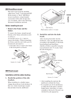
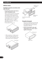
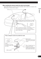
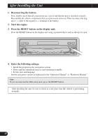
DIN Front/Rear-mount This unit can be properly installed either from "Front" (conventional DIN Front-mount) or "Rear" (DIN Rearmount installation, using threaded screw holes at the sides of unit chassis). For details, refer to the following illustrated installation methods. Before installing the unit • Remove the frame and the holder. To remove the frame, extend top and bottom of the frame outwards in order to unlock it. Loosen the screws (2 × 3 mm) to remove the holder. (When reattaching the frame, point the side with a groove downwards and attach it.) • It becomes easy to remove the frame if the front panel is released. Holder Screw (2 × 3 mm) Frame DIN Front-mount Installation with the rubber bushing 1. Decide the position of the side brackets. When installing in a shallow space, change the position of side brackets. In this case, stick conceal tape on parts that protrude from the dashboard. Conceal tape Side bracket Flush surface screw (5 × 6 mm) 2. Install the unit into the dashboard. After inserting the holder into the dashboard, select the appropriate tabs according to the thickness of the dashboard material and bend them. (Install as firmly as possible using the top and bottom tabs. To secure, bend the tabs 90 degrees.) Dashboard 182 53 Rubber bushing Screw Holder Side bracket Screw (2 × 3 mm) • After installing the unit into the dashboard, reattach the frame. • If you prefer an off-set installation in which the front panel is pushed further back, when there is a space available at the back of the unit, use AD-GA10 (sold separately). 24 Nederlands Italiano Français Deutsch Español English
-
 1
1 -
2
-
3
-
4
-
5
-
6
-
7
-
8
-
9
-
10
-
11
-
12
-
13
-
14
-
15
-
16
-
17
-
18
-
19
-
 20
20 -
 21
21 -
 22
22 -
 23
23 -
 24
24 -
 25
25 -
 26
26 -
 27
27 -
 28
28 -
 29
29 -
 30
30 -
31
-
32
-
33
-
34
-
35
-
36
-
37
-
38
-
39
-
40
-
41
-
42
-
43
-
44
-
45
-
46
-
47
-
48
-
49
-
50
-
51
-
52
-
53
-
54
-
55
-
56
-
57
-
58
-
59
-
60
-
61
 |
 |
