Pioneer AVIC N2 Other Manual - Page 6
Before installing the unit, To prevent damage - owners manual
 |
UPC - 012562735191
View all Pioneer AVIC N2 manuals
Add to My Manuals
Save this manual to your list of manuals |
Page 6 highlights
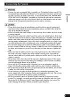
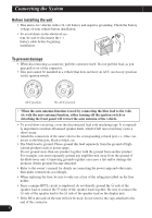
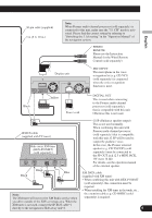
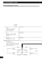
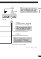
Connecting the System Before installing the unit • This unit is for vehicles with a 12-volt battery and negative grounding. Check the battery voltage of your vehicle before installation. • To avoid shorts in the electrical system, be sure to disconnect the (-) battery cable before beginning installation. To prevent damage • When disconnecting a connector, pull the connector itself. Do not pull the lead, as you may pull it out of the connector. • This unit cannot be installed in a vehicle that does not have an ACC (accessory) position on the ignition switch. F ACC O F O OF OF N STAR N STAR T T ACC position No ACC position • When the auto antenna function is used by connecting the blue lead to the vehicle with the auto antenna function, either turning off the ignition switch or detaching the front panel will retract the auto antenna of the vehicle. • To avoid short-circuiting, cover the disconnected lead with insulating tape. It is especially important to insulate all unused speaker leads, which if left uncovered may cause a short circuit. • Attach the connectors of the same color to the corresponding colored port, i.e., blue connector to the blue port, black to black, etc. • The black lead is ground. Please ground this lead separately from the ground of highcurrent products such as power amps. Do not ground more than one product together with the ground from another product. For example, you must separately ground any amplifier unit away from the ground of the Hide-away unit. Connecting grounds together can cause a fire and/or damage the products if their grounds became detached. • Refer to the owner's manual for details on connecting the power amp and other units, then make connections accordingly. • When replacing the fuse, be sure to only use a fuse of the rating prescribed on the fuse holder. • Since a unique BPTL circuit is employed, do not directly ground the ≠ side of the speaker lead or connect the ≠ sides of the speaker leads together. Be sure to connect the ≠ side of the speaker lead to the ≠ side of the speaker lead on the display unit. • If the RCA pin jack on the unit will not be used, do not remove the caps attached to the end of the connector. 5
-
 1
1 -
 2
2 -
 3
3 -
 4
4 -
 5
5 -
 6
6 -
 7
7 -
 8
8 -
 9
9 -
 10
10 -
 11
11 -
 12
12 -
13
-
14
-
15
-
16
-
17
-
18
-
19
-
20
-
21
-
22
-
23
-
24
-
25
-
26
-
27
-
28
-
29
-
30
-
31
-
32
-
33
-
34
-
35
-
36
-
37
-
38
-
39
-
40
-
41
-
42
-
43
-
44
-
45
-
46
-
47
-
48
-
49
-
50
-
51
-
52
-
53
-
54
-
55
-
56
-
57
-
58
-
59
-
60
-
61
 |
 |
