Pioneer FH-X700BT Owner's Manual - Page 17
Installation, Installing the microphone
 |
View all Pioneer FH-X700BT manuals
Add to My Manuals
Save this manual to your list of manuals |
Page 17 highlights
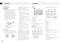
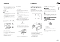
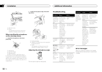
Installation Installation Section 03 English j When using a subwoofer of 70 W (2 W), be sure to connect the subwoofer to the violet and violet/black leads of this unit. Do not connect anything to the green and green/ black leads. k Not used. l Subwoofer (4 W) × 2 Notes ! With a 2 speaker system, do not connect anything to the speaker leads that are not connected to speakers. ! Change the initial menu of this unit. Refer to SP-P/O MODE (rear output and preout setting) on page 15. The subwoofer output of this unit is monaural. Power amp (sold separately) Perform these connections when using the optional amplifier. 1 3 2 4 5 5 3 1 2 6 7 7 Installation Important ! Check all connections and systems before final installation. ! Do not use unauthorized parts as this may cause malfunctions. ! Consult your dealer if installation requires drilling of holes or other modifications to the vehicle. ! Do not install this unit where: - it may interfere with operation of the vehicle. - it may cause injury to a passenger as a result of a sudden stop. ! The semiconductor laser will be damaged if it overheats. Install this unit away from hot places such as near the heater outlet. ! Optimum performance is obtained when the unit is installed at an angle of less than 60°. 60° ! When installing, to ensure proper heat dispersal when using this unit, make sure you leave ample space behind the rear panel and wrap any loose cables so they are not blocking the vents. 1 System remote control Connect to Blue/white cable. 2 Power amp (sold separately) 3 Connect with RCA cables (sold separately) 4 To Front output 5 Front speaker 6 To Rear output or subwoofer output 7 Rear speaker or subwoofer Leave ample space 5 cm 5 cm 5cm ! Use commercially available parts when installing. Installation using the screw holes on the side of the unit % Fastening the unit to the factory radiomounting bracket. Position the unit so that its screw holes are aligned with the screw holes of the bracket, and tighten the screws at 3 locations on each side. Installing the microphone CAUTION It is extremely dangerous to allow the microphone lead to become wound around the steering column or shift lever. Be sure to install the unit in such a way that it will not obstruct driving. Note Install the microphone in a position and orientation that will enable it to pick up the voice of the person operating the system. 1 2 When installing the microphone on the sun visor 1 Install the microphone on the microphone clip. 1 2 3 4 1 If the pawl gets in the way, bend it down. 2 Factory radio mounting bracket 3 Use either truss (5 mm × 8 mm) or flush sur- face (5 mm × 9 mm) screws, depending on the bracket screw holes. 4 Dashboard or console 1 Microphone 2 Microphone clip 2 Install the microphone clip on the sun visor. With the sun visor up, install the microphone clip. (Lowering the sun visor reduces the voice recognition rate.) En 17
-
 1
1 -
2
-
3
-
4
-
5
-
6
-
7
-
8
-
9
-
10
-
11
-
 12
12 -
 13
13 -
 14
14 -
 15
15 -
 16
16 -
 17
17 -
 18
18 -
 19
19 -
 20
20 -
 21
21 -
 22
22 -
23
-
24
-
25
-
26
-
27
-
28
-
29
-
30
-
31
-
32
-
33
-
34
-
35
-
36
-
37
-
38
-
39
-
40
-
41
-
42
-
43
-
44
-
45
-
46
-
47
-
48
-
49
-
50
-
51
-
52
-
53
-
54
-
55
-
56
-
57
-
58
-
59
-
60
-
61
-
62
-
63
-
64
-
65
-
66
-
67
-
68
-
69
-
70
-
71
-
72
-
73
-
74
-
75
-
76
 |
 |
