Pioneer SC-LX85 Operating Instructions - Page 10
Receiver, Adv Mcacc - av receiver
 |
View all Pioneer SC-LX85 manuals
Add to My Manuals
Save this manual to your list of manuals |
Page 10 highlights
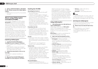
02 Controls and displays Remote control display The display lights when a remote control operation is performed, then turns off after 20 seconds if no other operation is performed. When in the Remote Setup mode, the setup is canceled and the display turns off if no operation is performed for 1 minute (page 64). Remote control display for infrared signal transmission (default) 1 23 4 5 6 MAIN IR SOURCE iPod/USB 7 Remote control display for RF twoway communications 1 23 4 5 6 MAIN RF RCV CTRL AV RECEIVER VIDEO +12.0dB 1. Adv MCACC 89 10 11 12 ! This is displayed when an RF adapter is connected to the receiver and paired with the remote control. For details, see Using the RF communications function on page 70. ! Depending on the communications environment, two-way communications may not work well and the remote control display may not reflect the receiver's status. 1 Remote control operating zone indicator This indicates which zone the remote control is currently set to operate. The display indicates the setting of the MULTI-ZONE operation selector switch. Only when RF two-way communications: The box display here indicates the communication status between this remote control unit and the receiver. MAIN (White box with black letters): Twoway communications are established and the receiver's power is on. MAIN (Gray box with black letters): Two-way communications are established and the receiver's power is off. MAIN (White letters only): Two-way communications are not working well. In this case, the area indicating the receiver's status (12) is not displayed. 2 Remote control code sending indicator This appears when signals are sent from the remote control. 3 Remote control code sending mode indicator This indicates whether remote control codes are being sent by infrared (IR) signal or RF communications. 4 Remote control operation indicator This indicates which operation mode the remote control is currently set to. The display indicates the setting of the remote control operation selector switch. 5 Input function and sending code indicator This indicates what input function can currently be operated with the remote control. Also, when a button is pressed and its operation code is sent, the name of that code is displayed. 6 Area indicating the remote control's status 7 Nothing displayed Nothing is displayed here when the remote control code sending mode is set to IR. 8 Scroll indicators Light when there are more selectable items when making the various settings. 9 Receiver input indicator This indicates the input function currently selected for the receiver's zone. 10 Receiver display The same information as on the receiver's display is displayed here. 11 Master volume display This indicates the volume of the receiver's main zone using, as an icon and in decibels (dB). When the sound is muted, the icon is displayed. 12 Area indicating the receiver's status RF adapter Front 1 2 Rear 3 1 LED 2 SETTING Use to pairing the RF adapter and remote control (page 71). 3 IR blaster terminals Connect the IR blaster cable (page 71). 10 En
-
 1
1 -
2
-
3
-
4
-
 5
5 -
 6
6 -
 7
7 -
 8
8 -
 9
9 -
 10
10 -
 11
11 -
 12
12 -
 13
13 -
 14
14 -
 15
15 -
16
-
17
-
18
-
19
-
20
-
21
-
22
-
23
-
24
-
25
-
26
-
27
-
28
-
29
-
30
-
31
-
32
-
33
-
34
-
35
-
36
-
37
-
38
-
39
-
40
-
41
-
42
-
43
-
44
-
45
-
46
-
47
-
48
-
49
-
50
-
51
-
52
-
53
-
54
-
55
-
56
-
57
-
58
-
59
-
60
-
61
-
62
-
63
-
64
-
65
-
66
-
67
-
68
-
69
-
70
-
71
-
72
-
73
-
74
-
75
-
76
-
77
-
78
-
79
-
80
-
81
-
82
-
83
-
84
-
85
-
86
-
87
-
88
-
89
-
90
-
91
-
92
-
93
-
94
-
95
-
96
-
97
-
98
-
99
-
100
-
101
-
102
-
103
-
104
-
105
-
106
-
107
-
108
-
109
-
110
-
111
-
112
-
113
-
114
-
115
-
116
-
117
-
118
-
119
-
120
-
121
-
122
 |
 |
