Pioneer SX-A9MK2-K Owner's Manual - Page 10
Connecting up, Connecting the speakers
 |
View all Pioneer SX-A9MK2-K manuals
Add to My Manuals
Save this manual to your list of manuals |
Page 10 highlights
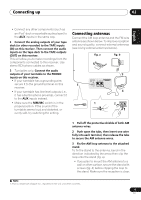
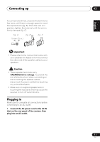
02 Connecting up 4 Place the AM antenna on a flat surface and in a direction giving the best reception. 5 Connect the FM wire antenna in the same way as the AM loop antenna. For best results, extend the FM antenna fully and fix to a wall or door frame. Don't drape loosely or leave coiled up. Using external antennas To improve FM reception Use a 75 Ω coaxial cable to connect an external FM antenna. Connecting the speakers Make sure you connect the speaker on the right to the right terminal and the speaker on the left to the left terminal. Also make sure the positive and negative (+/-) terminals on the receiver match those on the speakers. You can use speakers with a nominal impedance between 4 Ω to 16 Ω. Be sure to complete all connections before connecting this unit to the AC power source. Left speaker One-touch PAL connector FM UNBAL 75 AM LOOP ANTENNA 75 Ω coaxial cable To improve AM reception Connect a 5 m to 6 m (15 ft. to 18 ft.) length of vinyl-coated wire to the AM antenna terminal without disconnecting the supplied AM loop antenna. Outdoor antenna FM UNBAL 75 5 m to 6 m (15 ft. to 18 ft.) Indoor antenna (vinyl-coated wire) AM LOOP ANTENNA For the best possible reception, suspend horizontally outdoors. CONTROL OUT OUT SIGNAL GND L MM/MC R PHONO AC IN L SPEAKER • Connect the speakers to the speaker terminals as shown above. Connections for the left speaker are shown. Connect the right speaker in the same way. You can use either bare wire connections to do this (see below). Bare wire connections Make sure that the speaker cable you're going to use is properly prepared with about 10 mm (3/8 in.) of insulator stripped from each wire, and the exposed wire strands twisted together (fig. A). 10 En
-
 1
1 -
2
-
3
-
4
-
 5
5 -
 6
6 -
 7
7 -
 8
8 -
 9
9 -
 10
10 -
 11
11 -
 12
12 -
 13
13 -
 14
14 -
 15
15 -
16
-
17
-
18
-
19
-
20
-
21
-
22
-
23
-
24
-
25
-
26
-
27
-
28
-
29
-
30
-
31
-
32
-
33
-
34
-
35
-
36
-
37
-
38
-
39
-
40
-
41
-
42
-
43
-
44
-
45
-
46
-
47
-
48
-
49
-
50
-
51
-
52
-
53
 |
 |
