Polk Audio PA D4000.4 PA D4000.4 Owner's Manual - Page 3
Tools Of The Trade, End Panel Layouts - amplifier
 |
View all Polk Audio PA D4000.4 manuals
Add to My Manuals
Save this manual to your list of manuals |
Page 3 highlights
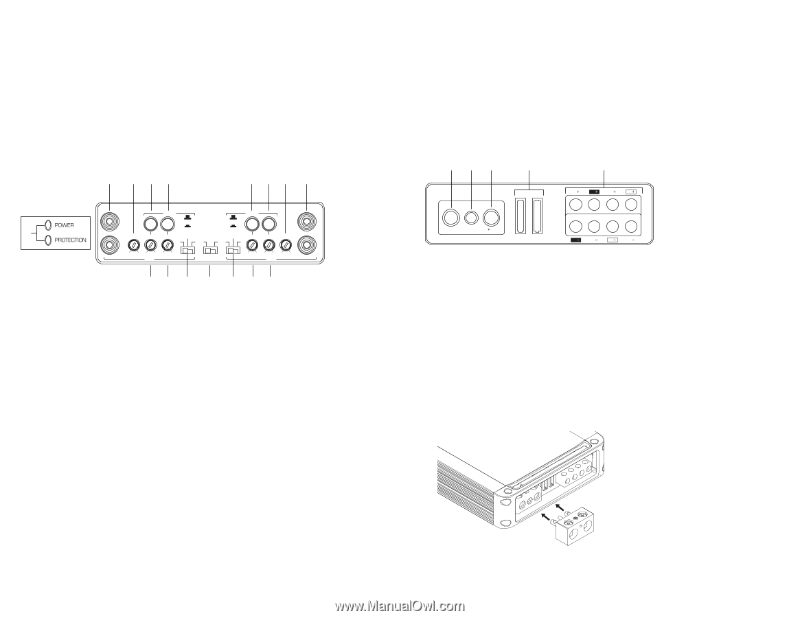
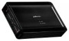
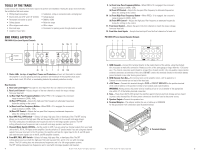
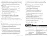
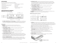
SUB UB INT SUB LEVEL SONIC REMOTE LEVEL CONTROL LPF INPUT FL RL TOOLS OF THE TRADE SOURCE INPUT SUB 6V 200mV 20Hz 38Hz 40Hz 220Hz SUB INT SUB LEVEL SONIC REMOTE LEVEL CONTROL LPF INPUT FL RL PA D5000.5 FULL HRPEFLtAhRise1teindsntaelxlat taiorFeUnLLHttPhhFBeaPFtFmROmNaTujocrhiteyaosfieStUhrB.e1 tooSlOsURrCeE quired CHANNEL MODE 6V 200mV REAR to perform 20Hz 38Hz an installation. FRONT 40Hz 220Hz Having the proper tools will make • Phillips head screwdriver 40Hz 4000Hz 6V 200mV HPF LEVEL 80Hz 4000Hz 40Hz 400Hz LPF HPF 6LVEVE20L0m4FVCUHLL HPF ST FR • HPF SolRFdRUeLL rleBPsF s, crimp-on connectCoHMArONsDNEEaL nd a crimping tool • Electric drill and 3/16" anSUdB 21/8" drill bits • Safety 40Hz 4000Hz 6V 200mV HPF LEVEL glasses 80Hz 4000Hz LPF 40Hz 400Hz HPF 6V 200mV LEVEL 4CH ST FR RR 9 1•0 Pe1r1mane1n2t ink m13arker14or pe1n5cil 16 • DMM or VOM • Safety glasses • Wire strippers and cutters 9 10 •11Nylon12tie str1a3ps 14 15 16 • Wire crimper • Electrical tape • Grommets for passing wires through metal car walls • Amplifier Power Wire End Panel Layouts 3 P4Aa D4050a0.4 Line Level Inputs/Co9natrols10a 11 12 2 3 4a 5a 9a 10a 11 12 X-OVER FREQ x 1 FREQ x 10 LEVEL HPF LPF FULL BPF HPF 1 6V 200mV 20Hz 400Hz 50Hz 500Hz REAR 4CH ST CHANNEL MODE 4b 5b 6 7 X-OVER FREQ x 1 L FREQ x 10 X-OVER FULL L LPF BPF HPF HPF LEVEL FREQ x 1 FREQ x 1R0 LEVEL HPF LPF 50Hz 500Hz 20Hz 400Hz 6V 200mV R FRONT FULL BPF HPF 4CH ST 6V 200mV 20Hz 400Hz 50Hz 500Hz REAR 8 9b 10b CHANNEL MODE FREQ x 1 X-OVER PA D4000.4L FREQ x 10 FULL LPF BPF HPF HPF LEVEL R 50Hz 500Hz 20Hz 400Hz 6V 200mV FRONT 4b 5b 6 7 8 9b 10b 1. Status LEDs (on top of amplifier): Power and Protection-Power will illuminate to indicate the amplifier is on and operating normally; protection will illuminate if the amplifier shuts down due to short circuit, DC offset, or overheating detected by onboard protection circuitry. Rear Controls 3a 2. R3bear Li4nae Lev4ebl Inputs-ac5cepts line6 level in7put from the rear channels of a head unit. 3. Rear Level Control-Adjusts the gain of the rear channels to match the output voltage from your head unit. 2 3a 3b 4a 4b 5 67 4. (a) Rear High-Pass Frequency ButItNoPUnT -WOUhTPeUTn FREQ x 10 is engaged, the crossover's range increases to 200Hz - 4kHz. BPF LPF HPF X -OVER(b) Rear HPF X-OVER FREQ x 1 LPF belFoREwQ x 1the Control-Adjusts tLhe sHePFtting on the LcEVoEnL trol. high pass LPF X-OVER filteLr frequency HPF X-OVER to attenuate freqINuPeUTnciPeAsODUTP2U0T 00.2 L L 15. (a) Rear Low-Pass FrequeHPnF cy BRuFRtEQtox 1n-LWPF henFRFERQRxE1 Q x 10HPF is engagedL,EVtELhe crossover's range increases to 500Hz - 5kHz. 50Hz 500Hz 20Hz 400Hz FREQ x 10 FREQ x 10 FULL6V B2P0F0mV R R (b) Rear LPF Control-Adjusts the low p50aHzs50s0Hzfilter frequ20eHzn40c0Hyz to attenu6Vat20e0mVfrequencies FREQ x 10 FREQ x 10 above the setting on the control. 6. Rear BPF, FULL, HPF Switch- Selects full range, high pass filter, or band-pass filter. The BPF setting allows you to use both the high pass filter and low pass filter, and it is for use with mid-range drivers. The FULL setting does not attenuate any frequencies and is for full range speaker systems. The HPF setting attenuates low frequencies and is used with mid-range speakers and tweeters. 7. Channel Mode Switch (ST/4Ch)-Set the switch to 4CH if you are using four channel outputs from your head unit to the FL, FR, RL, RR inputs on the amplifier. Set the switch to ST (stereo) mode if you are using two channel 2 3outputs 4from your 5head uni6t. In the ST 7position8, the amplifier will take the signal input to the FL and FR inputs and send the same signals also t2o the RL a3nd RR a4mplifier ch5annels. 6 78 8. Front BPF, FULL, HPF Switch-Selects full range, high pass filter, or band-pass filter. The BPF setting allows you to use both the high pass filter and low pass filter, and it is for use with mid-range drivers. The FULL setting does not attenuate any frequencies and is for full range speaker systems. The HPF setting attenuates low frequencies and is used with mid-range speakers andPtAwDe1e0te0r0s.1. 4 1 © 2011 Polk Audio-all rights reserved FRONT FRONT SUB RL RR FL FR SUB RL RR FL FR 9. (a) Front Low-Pass Frequency Button-When FREQ x 10 is engaged, the crossover's range increases to 500Hz - 5kHz. PA D 5000(bG.5N)D FronREtMLPF C12oV ntrol-Adjusts the low pass filter frequency to attenuate frequencies above the setting on40tAhe c4o0Antrol. SUB RL GND RR REM FL 12V FR 10 (a) Front High-Pass Frequency Button-When FREQ x 10 is en4g0Aaged4,0Athe crossSoUBver'sRL RR FL FR range increases to 200Hz - 4kHz. (b) Front HPF Control- Adjusts the high pass filter frequency to attenuate frequencies below the setting on the control. 11. Front Level Control-Adjusts the gain of the front channels to match the output voltage from your head unit. 12. Front Line Level Inputs-Accepts line level input from the front channels of a head unit. PA D4000.4 Power Inputs/Speaker Outputs 1 23 4 5 1 23 4 RL RR FL FR 5 RL RR FL FR REAR REAR PA D4000.4 GND REM 12V 40A 35A RL GND RR REM FL FR 12V 40A 35A RL RR FL FR 1. GND (Ground)-Connect this terminal directly to the metal chassis of the vehicle, using the shortest wire necessary to make this connection. Always use wire of the same gauge or larger than the +12V power wire. The chassis connection point should be scraped free of paint and dirt. Use only quality crimped and/or soldered connectors at both ends of this wire. DO NOT connect this terminal directly to the vehicle battery ground terminal or any other factory ground points. 2. REM (Remote Turn On)-This terminal turns on the amplifier when +12V is applied to it. Connect it to the remote turn on lead of the head unit. 3. +12V Power-Connect this terminal through a FUSE or CIRCUIT BREAKER to the positive terminal of the vehicle battery or the positive terminal of an isolated audio system battery. WA1RNIN2G: Alw3ays protect 4this power wire by installin5g a fuse or circuit breaker of the appropriate size within 12" of the battery terminal connec1tion. 2 3 4 5 4. Fuse-These fuses (40A & 35A) protect the amplifier against internal electrical damage and are meant to protect only the amplifier. All other power connectioBnRIsDGEsDhould be fused at the power source. 5. Speaker Output-Connect the speakers here BRIDGED 6. Terminal Adaptor-The adaptor enables the use of cable up to 0000AWG PA D2000fo.2rGNtDhe grRoEMund an12dV +12V connections (see illustration below). 25A 25A L L GND REM R R 12V 25A 25A L L R R 1 23 6. Terminal Adaptor 4 5 1 23 4 PA©D21001010.P1olk Audio-all rights reserved 5 5
-
 1
1 -
 2
2 -
 3
3 -
 4
4 -
 5
5 -
 6
6 -
 7
7 -
 8
8 -
 9
9 -
10
-
11
-
12
-
13
-
14
-
15
-
16
-
17
-
18
-
19
-
20
-
21
-
22
-
23
-
24
-
25
-
26
-
27
-
28
-
29
-
30
-
31
-
32
-
33
-
34
 |
 |