ProForm 935 E Elliptical English Manual - Page 29
How To Adjust The Drive Belt
 |
View all ProForm 935 E Elliptical manuals
Add to My Manuals
Save this manual to your list of manuals |
Page 29 highlights
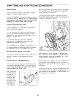
HOW TO ADJUST THE DRIVE BELT If the pedals slip while you are pedaling, even while the resistance is adjusted to the highest setting, the drive belt may need to be adjusted. To adjust the drive belt, first press the power switch to the off position and unplug the power cord. See EXPLODED DRAWING B on page 34. First, remove the M4 x 16mm Screw (61) from the Left Leg Inner Cover (39). Then, remove the Left Leg Inner Cover and the Left Leg Outer Cover (92). See EXPLODED DRAWING C on page 35. Remove all of the M4 x 16mm Screws (61) and M4 x 38mm Screws (64) from the Left and Right Shields (44, 45). Make sure to note which size Screws come from which holes. Then, carefully remove the Left Shield. Loosen the Idler Screw (97). Tighten the Idler Adjustment Screw (72) until the Drive Belt (46) is tight. When the Drive Belt is tight, retighten the Idler Screw. Next, remove the two M8 x 16mm Screws (76) and the two M8 Washers (33) from the Left Upper Body Leg (101) and the Left Pedal Arm (14). Then, remove the M8 x 14mm Shoulder Screw (81) from the Left Pedal Arm (14). Remove the Left Pedal Arm from the elliptical. 14 81 37 27 36 46 97 72 Remove the four M4 x 16mm Screws (not shown) from the Large Storage Foot (27), and then remove the Large Storage Foot. Remove the two M4 x 16mm Screws (not shown) from the Top Shield (37), and then use a flat screwdriver to pry the Top Shield upward off the elliptical. Then, pry the left Pedal Disc (36) off the elliptical. When you are finished, reattach the left shield, the left pedal disc, the top shield, the large storage foot, and the left pedal arm. Then, plug in the power cord. 29
-
 1
1 -
2
-
3
-
4
-
5
-
6
-
7
-
8
-
9
-
10
-
11
-
12
-
13
-
14
-
15
-
16
-
17
-
18
-
19
-
20
-
21
-
22
-
23
-
 24
24 -
 25
25 -
 26
26 -
 27
27 -
 28
28 -
 29
29 -
 30
30 -
 31
31 -
 32
32 -
 33
33 -
 34
34 -
35
-
36
 |
 |
