ProForm Endurance 720 E Instruction Manual - Page 11
Roller Arm.
 |
View all ProForm Endurance 720 E manuals
Add to My Manuals
Save this manual to your list of manuals |
Page 11 highlights
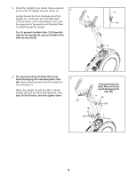
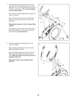
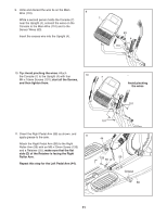
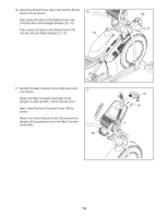
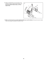
9. Untie and discard the wire tie on the Main Wire (110). 9 While a second person holds the Console (7) 7 near the Upright (4), connect the wires on the Console to the Main Wire (110) and to the Sensor Wires (63). Insert the excess wire into the Upright (4). 63 4 110 10. Tip: Avoid pinching the wires. Attach the Console (7) to the Upright (4) with four 10 7 M4 x 16mm Screws (101); start all the Screws, and then tighten them. Avoid pinching the wires 4 101 11. Orient the Right Pedal Arm (58) as shown, and apply grease to the axle. 11 Attach the Right Pedal Arm (58) to the Right Roller Arm (59) with an M8 x 20mm Screw (126) and a Retainer (55); make sure that the flat side (D) of the Retainer is facing the Right Roller Arm. Repeat this step for the Left Pedal Arm (44). 101 44 126 55 D 59 Grease 58 11
-
 1
1 -
2
-
3
-
4
-
5
-
 6
6 -
 7
7 -
 8
8 -
 9
9 -
 10
10 -
 11
11 -
 12
12 -
 13
13 -
 14
14 -
 15
15 -
 16
16 -
17
-
18
-
19
-
20
-
21
-
22
-
23
-
24
-
25
-
26
-
27
-
28
-
29
-
30
-
31
-
32
-
33
-
34
-
35
-
36
 |
 |
