ProForm Endurance 720 E Instruction Manual - Page 29
How To Adjust The Drive Belt
 |
View all ProForm Endurance 720 E manuals
Add to My Manuals
Save this manual to your list of manuals |
Page 29 highlights
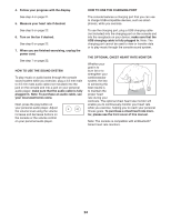
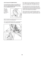
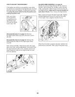
HOW TO ADJUST THE DRIVE BELT If the pedals slip while you are pedaling, even while the resistance is adjusted to the highest level, the drive belt may need to be adjusted. To adjust the drive belt, first press the power switch to the off position and unplug the power cord. Next, use a stan- dard screwdriver 118 to carefully pry off the Shield Cover 75 (75) and the Shield Cover Cap (118). See EXPLODED DRAWING C on page 35. Identify the Left and Right Shields (73, 74). Remove the M4 x 19mm Screws (5), the M4 x 25mm Screws (139), and the M4 x 48mm Screw (107) from the Left and Right Shields; make sure to note the location of each size of Screw. Then, remove the Right Shield. Next, locate and loosen the Idler Screw (89). Tighten the Belt Adjustment Screw (91) until the Drive Belt (113) is tight. Then, retighten the Idler Screw. 113 See assembly step 15 on page 13. Remove the Right Upper Body Leg Outer and Inner Covers (69, 83). See assembly step 12 on page 12. Remove the Right Pedal Arm (58) from the Right Upper Body Leg (60). Next, remove the M8 x 16mm Screw (95), the Large Axle Cover (53), and the M8 Washer (not shown) from the right Crank Arm (20). Then, carefully remove the Right Pedal Arm (58) and the Right Roller Arm (59) from the elliptical. 89 91 When the drive belt is properly adjusted, reattach the parts that you removed. Then, plug in the power cord. 20 53 59 95 58 29
-
 1
1 -
2
-
3
-
4
-
5
-
6
-
7
-
8
-
9
-
10
-
11
-
12
-
13
-
14
-
15
-
16
-
17
-
18
-
19
-
20
-
21
-
22
-
23
-
 24
24 -
 25
25 -
 26
26 -
 27
27 -
 28
28 -
 29
29 -
 30
30 -
 31
31 -
 32
32 -
 33
33 -
 34
34 -
35
-
36
 |
 |
