Ryobi RTS10G User Manual - Page 15
To Install/replace The Blade, Warning, Caution
 |
View all Ryobi RTS10G manuals
Add to My Manuals
Save this manual to your list of manuals |
Page 15 highlights
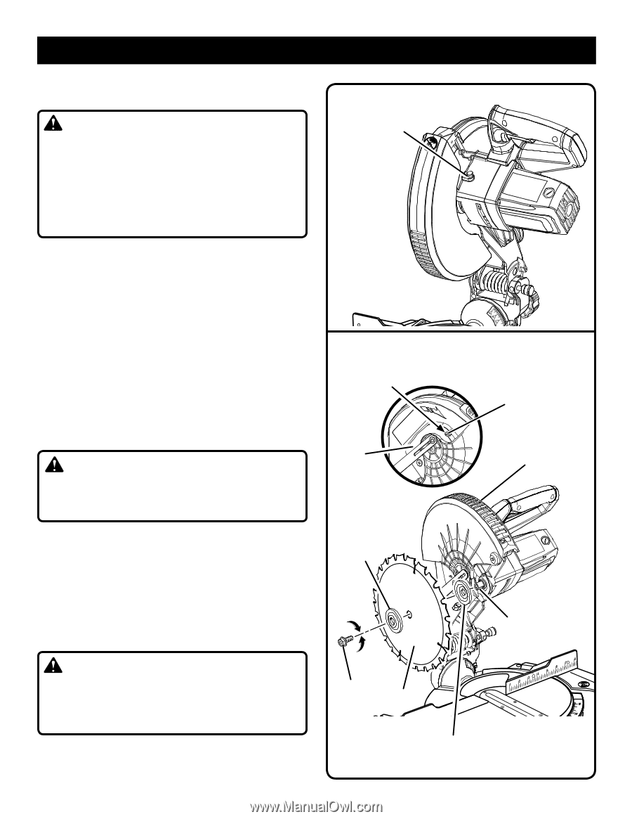
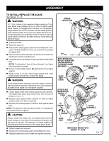
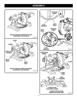
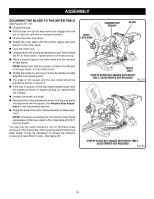
ASSEMBLY TO INSTALL/REPLACE THE BLADE See Figures 14 - 15. WARNING: A 7-1/4 in. blade is the maximum blade capacity of the saw. Never use a blade that is too thick to allow outer blade washer to engage with the flats on the spindle. Larger blades will come in contact with the blade guards, while thicker blades will prevent the blade bolt from securing the blade on the spindle. Either of these situations could result in a serious accident and can cause serious personal injury. SPINDLE LOCK BUTTON Unplug the saw. Raise the saw arm. Rotate lower blade guard up and remove blade bolt cover screw. Rotate blade bolt cover up and back to expose the blade bolt. Depress and hold the spindle lock button and rotate the blade bolt until the spindle locks. Using the wrench provided, loosen and remove the blade bolt. NOTE: The blade bolt has left hand threads. Turn blade bolt clockwise to loosen. Remove outer blade washer. Do not remove inner blade washer. Wipe a drop of oil onto inner blade washer and outer blade washer where they contact the blade. WARNING: If inner blade washer has been removed, replace it before placing blade on spindle. Failure to do so could cause an accident since blade will not tighten properly. Fit saw blade inside lower blade guard and onto spindle. The blade teeth point downward at the front of saw as shown in figure 15. Replace outer blade washer. Double "D" flats on blade washers align with flats on spindle. Depress and hold spindle lock button and replace blade bolt. NOTE: The blade bolt has left hand threads. Turn blade bolt counterclockwise to tighten. CAUTION: Always install the blade with the blade teeth and the arrow printed on the side of the blade pointing down at the front of the saw. The direction of blade rotation is also stamped with an arrow on the upper blade guard. NOTE: BEFORE USE, REPLACE SCREW AND TIGHTEN SECURELY TO PREVENT GUARD MOVEMENT BLADE BOLT COVER OUTER BLADE WASHER WITH DOUBLE "D" FLATS TO LOOSEN TO TIGHTEN BLADE BOLT BLADE Fig. 14 BLADE BOLT COVER SCREW LOWER BLADE GUARD FLAT(S) ON SPINDLE 22.5 31.6 Tighten blade bolt securely. Replace the lower blade guard and blade bolt cover. Replace blade bolt cover screw and tighten securely. 15 INNER BLADE WASHER WITH 31.6 22.5 DOUBLE "D" FLATS Fig. 15
-
 1
1 -
2
-
3
-
4
-
5
-
6
-
7
-
8
-
9
-
 10
10 -
 11
11 -
 12
12 -
 13
13 -
 14
14 -
 15
15 -
 16
16 -
 17
17 -
 18
18 -
 19
19 -
 20
20 -
21
-
22
-
23
-
24
-
25
-
26
-
27
-
28
-
29
-
30
-
31
-
32
-
33
-
34
-
35
-
36
-
37
-
38
-
39
-
40
-
41
-
42
-
43
-
44
-
45
-
46
-
47
-
48
-
49
-
50
-
51
-
52
-
53
-
54
-
55
-
56
-
57
-
58
-
59
-
60
-
61
-
62
-
63
-
64
-
65
-
66
-
67
-
68
-
69
-
70
-
71
-
72
-
73
-
74
-
75
-
76
-
77
-
78
-
79
-
80
-
81
-
82
-
83
-
84
 |
 |