Ryobi RTS10G User Manual - Page 18
Squaring The Blade To The Miter Table
 |
View all Ryobi RTS10G manuals
Add to My Manuals
Save this manual to your list of manuals |
Page 18 highlights
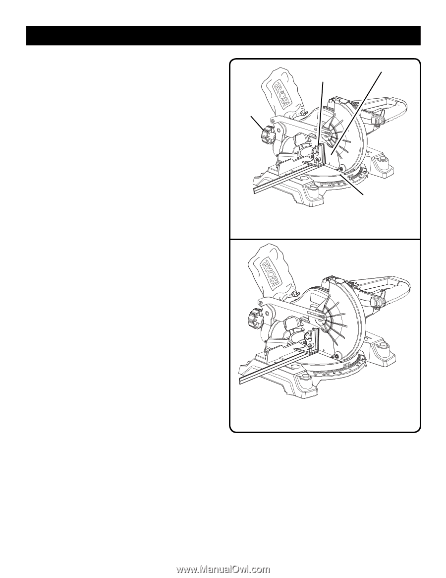
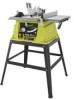
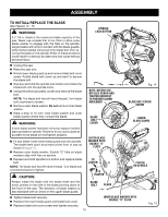
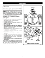
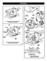
ASSEMBLY SQUARING THE BLADE TO THE MITER TABLE See Figures 19 - 23. Unplug the saw. Pull the saw arm all the way down and engage the lock pin to hold the saw arm in transport position. Unlock the miter lock lever. Rotate the miter table until the pointer aligns with zero detent on the miter scale. Lock the miter lock. Loosen bevel lock knob and set saw arm at 0° bevel (blade set 90° to miter table). Tighten bevel lock knob at stop. Place a square against the miter table and the flat part of saw blade. NOTE: Make sure that the square contacts the flat part of the saw blade, not the blade teeth. Rotate the blade by hand and check the blade-to-table alignment at several points. The edge of the square and the saw blade should be parallel as shown in figure 21. If the top or bottom of the saw blade angles away from the square as shown in figures 22 and 23, adjustments are needed. Loosen the bevel lock knob. Adjust positive stop adjustment screw to bring saw blade into alignment with the square. See Positive Stop Adjustment in the Adjustments section. Retighten bevel lock knob. Recheck blade-to-table alignment. NOTE: The above procedure can be used to check blade squareness of the saw blade to the miter table at both 0° and 45° angles. The saw has two scale indicators, one on the bevel scale and one on the miter scale. After squaring adjustments have been made, it may be necessary to loosen the indicator screws and reset them to zero. See figure 20. BEVEL LOCK KNOB COMBINATION SQUARE BLADE MITER TABLE VIEW OF BLADE NOT SQUARE WITH MITER TABLE, ADJUSTMENTS ARE REQUIRED Fig. 22 VIEW OF BLADE NOT SQUARE WITH MITER TABLE, ADJUSTMENTS ARE REQUIRED Fig. 23 18
-
 1
1 -
2
-
3
-
4
-
5
-
6
-
7
-
8
-
9
-
10
-
11
-
12
-
 13
13 -
 14
14 -
 15
15 -
 16
16 -
 17
17 -
 18
18 -
 19
19 -
 20
20 -
 21
21 -
 22
22 -
 23
23 -
24
-
25
-
26
-
27
-
28
-
29
-
30
-
31
-
32
-
33
-
34
-
35
-
36
-
37
-
38
-
39
-
40
-
41
-
42
-
43
-
44
-
45
-
46
-
47
-
48
-
49
-
50
-
51
-
52
-
53
-
54
-
55
-
56
-
57
-
58
-
59
-
60
-
61
-
62
-
63
-
64
-
65
-
66
-
67
-
68
-
69
-
70
-
71
-
72
-
73
-
74
-
75
-
76
-
77
-
78
-
79
-
80
-
81
-
82
-
83
-
84
 |
 |