Ryobi RTS10G User Manual - Page 20
To Bevel Cut
 |
View all Ryobi RTS10G manuals
Add to My Manuals
Save this manual to your list of manuals |
Page 20 highlights
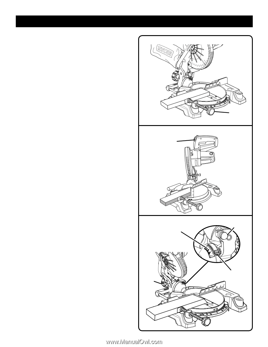
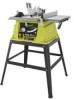
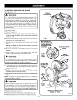
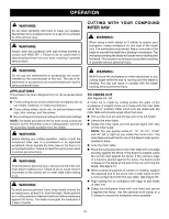
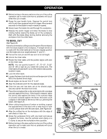
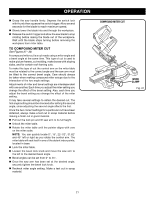
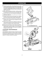
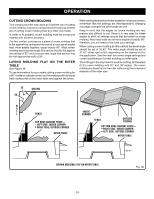
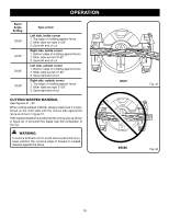
OPERATION Before turning on the saw, perform a dry run of the cutting operation just to make sure that no problems will occur when the cut is made. Grasp the saw handle firmly. Depress the switch lock with thumb then squeeze the switch trigger. Allow several seconds for the blade to reach maximum speed. Slowly lower the blade into and through the workpiece. Release the switch trigger and allow the blade to stop rotating before raising the blade out of the workpiece. Wait until the blade stops turning before removing the workpiece from the miter table. TO BEVEL CUT See Figure 26. A bevel cut is made by cutting across the grain of the workpiece with the blade angled to the workpiece. A straight bevel cut is made with the miter table set at the zero degree position and the blade set at an angle between 0° and 45°. Pull out the lock pin and lift saw arm to its full height. Unlock the miter table. Rotate the miter table until the pointer aligns with zero on the miter scale. NOTE: You can quickly locate 0°, 15°, 22-1/2°, 31.62° and 45° left or right as you rotate the control arm. The miter table will seat itself in one of the detent index points, located in base. Lock the miter table. Loosen the bevel lock knob and move the saw arm to the left to the desired bevel angle. Bevel angles can be set from 0° to 45°. Align the indicator point for the desired angle. Once the saw arm has been set at the desired angle, securely tighten the bevel lock knob. Place the workpiece flat on the miter table with one edge securely against the fence. If the board is warped, place the convex side against the fence. If the concave edge of a board is placed against the fence, the board could collapse on the blade at the end of the cut, jamming the blade. See figure 31. When cutting long pieces of lumber or molding, support the opposite end of the stock with a roller stand or with a work surface level with the saw table. See Figure 29. Align the cutting line on the workpiece with the edge of saw blade or laser line. Grasp the workpiece firmly with one hand and secure it against the fence. Use the optional work clamp or a C-clamp to secure the workpiece when possible. Before turning on the saw, perform a dry run of the cutting operation just to make sure that no problems will occur when the cut is made. CROSS CUT SWITCH LOCK MITER CUT BEVEL CUT BEVEL SCALE BEVEL LOCK KNOB 20 WORK CLAMP Fig. 24 Fig. 25 LOCK PIN INDICATOR POINT Fig. 26
-
 1
1 -
2
-
3
-
4
-
5
-
6
-
7
-
8
-
9
-
10
-
11
-
12
-
13
-
14
-
 15
15 -
 16
16 -
 17
17 -
 18
18 -
 19
19 -
 20
20 -
 21
21 -
 22
22 -
 23
23 -
 24
24 -
 25
25 -
26
-
27
-
28
-
29
-
30
-
31
-
32
-
33
-
34
-
35
-
36
-
37
-
38
-
39
-
40
-
41
-
42
-
43
-
44
-
45
-
46
-
47
-
48
-
49
-
50
-
51
-
52
-
53
-
54
-
55
-
56
-
57
-
58
-
59
-
60
-
61
-
62
-
63
-
64
-
65
-
66
-
67
-
68
-
69
-
70
-
71
-
72
-
73
-
74
-
75
-
76
-
77
-
78
-
79
-
80
-
81
-
82
-
83
-
84
 |
 |