Ryobi RTS10G User Manual - Page 27
Danger, Warning, To Adjust The Laser Guide, To Adjust The Miter Lock Lever
 |
View all Ryobi RTS10G manuals
Add to My Manuals
Save this manual to your list of manuals |
Page 27 highlights
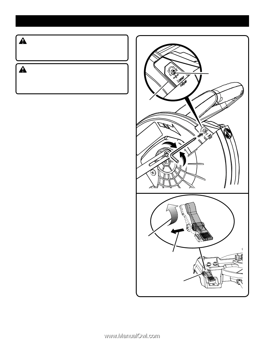
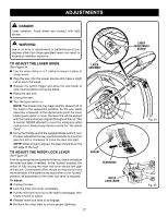
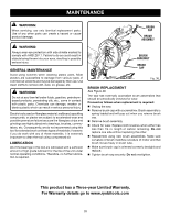
ADJUSTMENTS DANGER: Laser radiation. Avoid direct eye contact with light source. WARNING: Use of controls or adjustments or performance of procedures other than those specified herein can result in hazardous radiation exposure. TO ADJUST THE LASER GUIDE See Figure 34. Use the work clamp or a C-clamp to secure a piece of scrap wood. Plug the saw into the power source and make a slight cut to score the wood. Release the switch trigger and allow the saw blade to stop rotating before raising the blade. Raise the saw arm. Unplug the saw. Turn the laser switch on. NOTE: The broken line may begin slightly skewed off of the mark in the uppermost position. As the saw blade assembly is lowered, at the approximate point the lower blade guard starts to move, the laser line will be aligned with the mark and remain aligned throughout the cut. This is normal. NEVER attempt to move the workpiece while making a cut. Always keep hands outside the "No Hands Zone". Using the Phillips end of the supplied blade wrench, turn the laser adjustment screw counterclockwise to move the laser line left or clockwise to move the laser line right. NOTE: When properly aligned, the laser should be on the left edge of the kerf. TO ADJUST THE MITER LOCK LEVER See Figure 35. Prior to squaring the saw blade to the fence, check and adjust the miter lock lever, if needed. In the "locked" position, the action of fully locking the miter lock lever should feel tight and secure. Considerable effort should be required to move the miter table. If the table moves easily when in the "locked" position, an adjustment of the miter lock lever is required. To adjust: Unplug the saw. Lock the miter lock lever completely. Pull the miter lock lever out to the right to disengage, then rotate forward to adjust. Release miter lock lever to re-engage Recheck the miter table to ensure proper tightness. LASER ASSEMBLY ADJUST DESENGAGE MITER LOCK LEVER 27 LASER ADJUSTMENT SCREW Fig. 34 Fig. 35
-
 1
1 -
2
-
3
-
4
-
5
-
6
-
7
-
8
-
9
-
10
-
11
-
12
-
13
-
14
-
15
-
16
-
17
-
18
-
19
-
20
-
21
-
 22
22 -
 23
23 -
 24
24 -
 25
25 -
 26
26 -
 27
27 -
 28
28 -
 29
29 -
 30
30 -
 31
31 -
 32
32 -
33
-
34
-
35
-
36
-
37
-
38
-
39
-
40
-
41
-
42
-
43
-
44
-
45
-
46
-
47
-
48
-
49
-
50
-
51
-
52
-
53
-
54
-
55
-
56
-
57
-
58
-
59
-
60
-
61
-
62
-
63
-
64
-
65
-
66
-
67
-
68
-
69
-
70
-
71
-
72
-
73
-
74
-
75
-
76
-
77
-
78
-
79
-
80
-
81
-
82
-
83
-
84
 |
 |