Ryobi RTS10G User Manual - Page 21
To Compound Miter Cut - blade change
 |
View all Ryobi RTS10G manuals
Add to My Manuals
Save this manual to your list of manuals |
Page 21 highlights
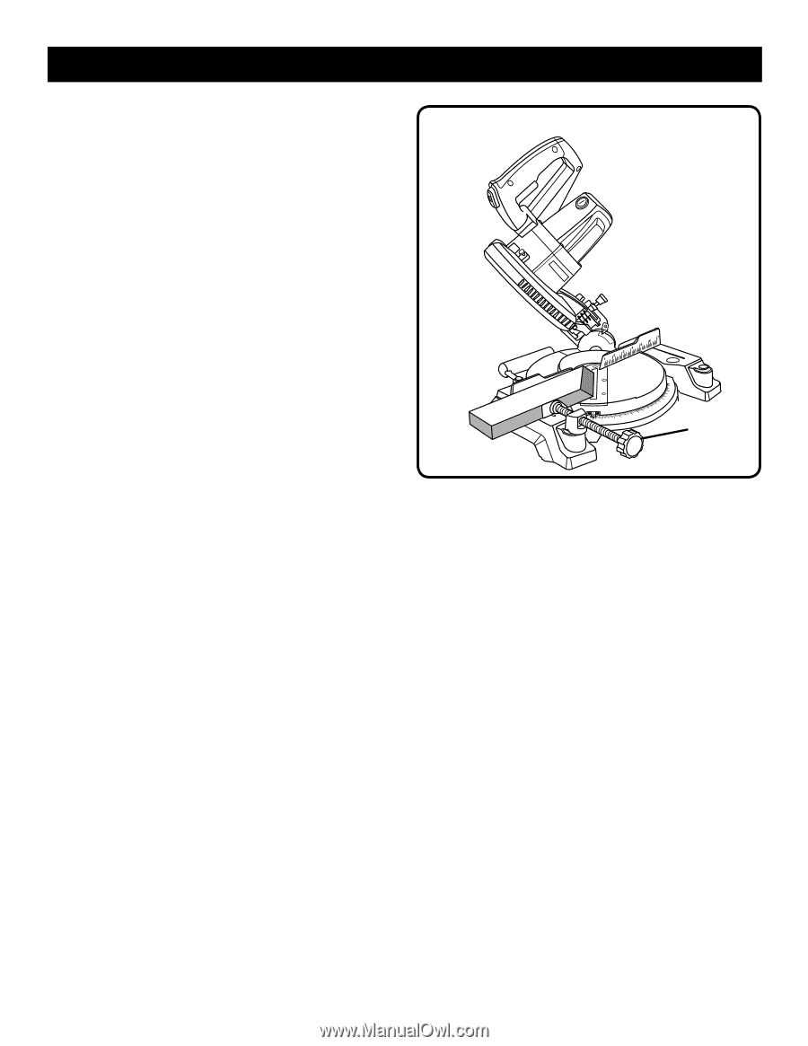
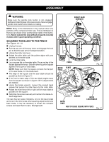
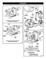
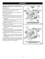
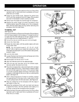
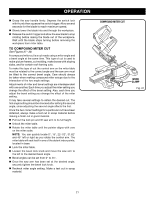
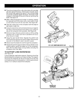
OPERATION Grasp the saw handle firmly. Depress the switch lock with thumb then squeeze the switch trigger. Allow several seconds for the blade to reach maximum speed. Slowly lower the blade into and through the workpiece. Release the switch trigger and allow the saw blade to stop rotating before raising the blade out of the workpiece. Wait until the blade stops turning before removing the workpiece from miter table. TO COMPOUND MITER CUT See Figures 27 - 28. A compound miter cut is a cut made using a miter angle and a bevel angle at the same time. This type of cut is used to make picture frames, cut molding, make boxes with sloping sides, and for certain roof framing cuts. To make this type of cut the control arm on the miter table must be rotated to the correct angle and the saw arm must be tilted to the correct bevel angle. Care should always be taken when making compound miter setups due to the interaction of the two angle settings. Adjustments of miter and bevel settings are interdependent with one another. Each time you adjust the miter setting you change the effect of the bevel setting. Also, each time you adjust the bevel setting you change the effect of the miter setting. It may take several settings to obtain the desired cut. The first angle setting should be checked after setting the second angle, since adjusting the second angle affects the first. Once the two correct settings for a particular cut have been obtained, always make a test cut in scrap material before making a finish cut in good material. Pull out the lock pin and lift saw arm to its full height. Unlock the miter table. Rotate the miter table until the pointer aligns with zero on the miter scale. NOTE: You can quickly locate 0°, 15°, 22-1/2°, 31.62° and 45° left or right as you rotate the control arm. The miter table will seat itself in one of the detent index points, located in base. Lock the miter table. Loosen the bevel lock knob and move the saw arm to the left to the desired bevel angle. Bevel angles can be set from 0° to 45°. Once the saw arm has been set at the desired angle, securely tighten the bevel lock knob. Recheck miter angle setting. Make a test cut in scrap material. COMPOUND MITER CUT WORK CLAMP Fig. 27 21
-
 1
1 -
2
-
3
-
4
-
5
-
6
-
7
-
8
-
9
-
10
-
11
-
12
-
13
-
14
-
15
-
 16
16 -
 17
17 -
 18
18 -
 19
19 -
 20
20 -
 21
21 -
 22
22 -
 23
23 -
 24
24 -
 25
25 -
 26
26 -
27
-
28
-
29
-
30
-
31
-
32
-
33
-
34
-
35
-
36
-
37
-
38
-
39
-
40
-
41
-
42
-
43
-
44
-
45
-
46
-
47
-
48
-
49
-
50
-
51
-
52
-
53
-
54
-
55
-
56
-
57
-
58
-
59
-
60
-
61
-
62
-
63
-
64
-
65
-
66
-
67
-
68
-
69
-
70
-
71
-
72
-
73
-
74
-
75
-
76
-
77
-
78
-
79
-
80
-
81
-
82
-
83
-
84
 |
 |