Samsung LS40BHPNB/XAA User Manual (ENGLISH) - Page 37
Connections, SyncMaster 400PXn/460PXn, Installing the Stand KIT
 |
View all Samsung LS40BHPNB/XAA manuals
Add to My Manuals
Save this manual to your list of manuals |
Page 37 highlights
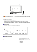
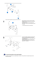
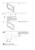
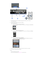
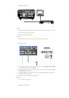
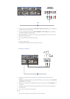
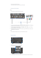
SyncMaster 400PXn/460PXn Select Language Main Page Model Safety Instructions Introduction Connections Installing the Stand KIT Connecting the LCD Display Using the Software Adjusting the LCD Display Troubleshooting Specifications Information Appendix The color and appearance of the product may vary depending on the model, and the product specifications are subject to change without prior notice for reasons of performance enhancement. Connections Installing the Stand KIT Note • Only the supplied bolts should be used. Caution Samsung Electronics will not be responsible for damages caused by using a base other than those specified. Installing the Semi Stand Left stand Caution Right stand Make sure to install the stand with the Caution label folded backwards. 1) A 'Cover-Protector' is used to protect the hole at the bottom of the LCD Display , where the stand is inserted. Be sure to remove the 'Cover-Protector' when attaching the provided Semi Stand or Stand KIT (sold separately) and cover the hole using the 'Cover-Hole' when attaching the wall mount kit. 2) Set up the left and right stands respectively. 3) Insert the stand into the hole at the bottom of the LCD Display. Insert the screw into the hole indicated and tighten it. (M4 x L15) Caution
-
 1
1 -
2
-
3
-
4
-
5
-
6
-
7
-
8
-
9
-
10
-
11
-
12
-
13
-
14
-
15
-
16
-
17
-
18
-
19
-
20
-
21
-
22
-
23
-
24
-
25
-
26
-
27
-
28
-
29
-
30
-
31
-
 32
32 -
 33
33 -
 34
34 -
 35
35 -
 36
36 -
 37
37 -
 38
38 -
 39
39 -
 40
40 -
 41
41 -
 42
42 -
43
-
44
-
45
-
46
-
47
-
48
-
49
-
50
-
51
-
52
-
53
-
54
-
55
-
56
-
57
-
58
-
59
-
60
-
61
-
62
-
63
-
64
-
65
-
66
-
67
-
68
-
69
-
70
-
71
-
72
-
73
-
74
-
75
-
76
-
77
-
78
-
79
-
80
-
81
-
82
-
83
-
84
-
85
-
86
-
87
-
88
-
89
-
90
-
91
-
92
-
93
-
94
-
95
-
96
-
97
-
98
-
99
-
100
-
101
-
102
-
103
-
104
-
105
-
106
-
107
-
108
-
109
-
110
-
111
-
112
-
113
-
114
-
115
-
116
-
117
-
118
-
119
-
120
-
121
-
122
-
123
-
124
-
125
-
126
-
127
-
128
-
129
-
130
-
131
-
132
-
133
-
134
-
135
-
136
-
137
-
138
-
139
-
140
-
141
-
142
-
143
-
144
-
145
-
146
-
147
-
148
-
149
-
150
-
151
-
152
-
153
-
154
-
155
-
156
-
157
-
158
-
159
-
160
-
161
-
162
-
163
-
164
-
165
-
166
-
167
-
168
-
169
-
170
-
171
-
172
-
173
-
174
-
175
-
176
 |
 |