Sanyo PLC-HF15000L Owner's Manual - Page 11
Terminals and Connectors, SERIAL PORT OUT TERMINAL - hd
 |
View all Sanyo PLC-HF15000L manuals
Add to My Manuals
Save this manual to your list of manuals |
Page 11 highlights
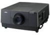
Terminals and Connectors Part Names and Functions q w e r t !0 o i u y q SERIAL PORT IN TERMINAL If you control the projector from a computer, you must connect a cable (not supplied) from your computer to this RS-232C terminal. w SERIAL PORT OUT TERMINAL This terminal outputs signal from SERIAL PORT IN. More than two projectors can be controlled with one computer by connecting SERIAL PORT IN of another projector to this RS-232C terminal. e USB CONNECTOR (series B) USB connector is to used to service the projector. r R/C JACK When using the wired remote control, connect the wired remote control to this jack with a remote control cable (not supplied). t LAN PORT Connecting the Ethernet cable See the owner's manual of "Network Set-up and Operation" for details. y S-VIDEO JACK Connects the S-VIDEO output signal from video equipment to this jack (p.21). u 5 BNC JACK Connects the component or composite video output signal from video equipment to VIDEO/Y, Pb/Cb, and Pr/Cr jacks or connect the computer output signal (5 BNC Type [Green, Blue, Red, Horiz. Sync, and Vert. Sync.]) to G, B, R, H/HV, and V jacks (pp.20-21). i ANALOG TERMINAL Connects the computer (or RGB scart) output signal to this terminal (pp.20-21). o HDMI TERMINAL Connects the HDMI output signal from video equipment to this terminal. (pp.20-21) !0 DIGITAL (DVI-D) TERMINAL Connects computer output (Digital/DVI-D type) to this terminal (p.20). HD (HDCP Compatible) signal can be also connected (p.21). 11
-
 1
1 -
2
-
3
-
4
-
5
-
 6
6 -
 7
7 -
 8
8 -
 9
9 -
 10
10 -
 11
11 -
 12
12 -
 13
13 -
 14
14 -
 15
15 -
 16
16 -
17
-
18
-
19
-
20
-
21
-
22
-
23
-
24
-
25
-
26
-
27
-
28
-
29
-
30
-
31
-
32
-
33
-
34
-
35
-
36
-
37
-
38
-
39
-
40
-
41
-
42
-
43
-
44
-
45
-
46
-
47
-
48
-
49
-
50
-
51
-
52
-
53
-
54
-
55
-
56
-
57
-
58
-
59
-
60
-
61
-
62
-
63
-
64
-
65
-
66
-
67
-
68
-
69
-
70
-
71
-
72
-
73
-
74
-
75
-
76
-
77
-
78
-
79
-
80
-
81
-
82
-
83
-
84
-
85
-
86
-
87
-
88
-
89
-
90
-
91
-
92
-
93
-
94
-
95
-
96
-
97
-
98
-
99
-
100
 |
 |
