Seagate ST800FM0022 Pulsar.2 SAS Product Manual - Page 29
General DC power requirement notes.
 |
View all Seagate ST800FM0022 manuals
Add to My Manuals
Save this manual to your list of manuals |
Page 29 highlights
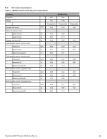
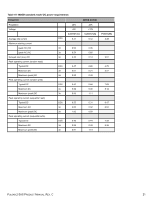
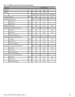
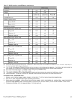
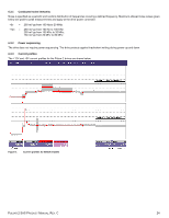
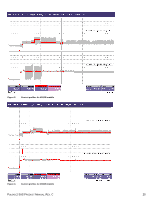
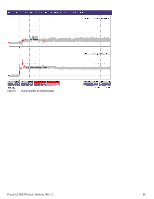
Table 12 100GB standard model DC power requirements PARAMETER 100GB (6.0GB) Regulation ±5% ±5% Voltage +5V +12V CURRENT (A) CURRENT (A) POWER (W) Average idle current DC 0.43 0.12 3.59 Maximum starting current (peak DC) DC 3σ 0.48 0.32 (peak AC) AC 3σ 1.53 0.61 Delayed start (max) DC 3σ 0.45 0.13 2.38 Peak operating current (random read): Typical DC DC 0.50 0.18 4.66 Maximum DC 3σ 0.51 0.20 4.95 Maximum (peak) DC 3σ 0.88 0.47 Peak operating current (random write) Typical DC DC 0.49 0.36 6.77 Maximum DC 3σ 0.51 0.39 7.23 Maximum (peak) DC 3σ 0.80 0.89 Peak operating current (sequential read) Typical DC DC 0.56 0.26 5.92 Maximum DC 3σ 0.59 0.29 6.43 Maximum (peak) DC 3σ 0.89 0.56 Peak operating current (sequential write) Typical DC DC 0.50 0.35 6.70 Maximum DC 3σ 0.52 0.38 7.16 Maximum (peak) DC 3σ 0.83 0.94 [1] Measured with average reading DC ammeter. Instantaneous +12V current peaks will exceed these values. Power supply at nominal voltage. N (number of drives tested) = 6, 60 Degrees C ambient. [2] For +12 V, a -10% tolerance is allowed during initial start but must return to ±5% before reaching ready state. The ±5% must be maintained after the drive signifies that its power-up sequence has been completed and that the drive is able to accept selection by the host initiator. [3] See +12V current profile in Figure 6 (for 400GB models) and Figure 7 (for 200GB models). [4] See +12V current profile in Figure 8 (for 100GB models). [5] This condition occurs after OOB and Speed Negotiation completes but before the drive has received the Notify Spinup primitive. [6] See paragraph 6.3.1, "Conducted noise immunity." Specified voltage tolerance includes ripple, noise, and transient response. General DC power requirement notes. 1. Minimum current loading for each supply voltage is not less than 1.7% of the maximum operating current shown. 2. The +5V and +12V supplies should employ separate ground returns. 3. Where power is provided to multiple drives from a common supply, careful consideration for individual drive power requirements should be noted. Where multiple units are powered on simultaneously, the peak starting current must be available to each device. 4. Parameters, other than start, are measured after a 10-minute warm up. PULSAR.2 SAS PRODUCT MANUAL, REV. C 23
-
 1
1 -
2
-
3
-
4
-
5
-
6
-
7
-
8
-
9
-
10
-
11
-
12
-
13
-
14
-
15
-
16
-
17
-
18
-
19
-
20
-
21
-
22
-
23
-
 24
24 -
 25
25 -
 26
26 -
 27
27 -
 28
28 -
 29
29 -
 30
30 -
 31
31 -
 32
32 -
 33
33 -
 34
34 -
35
-
36
-
37
-
38
-
39
-
40
-
41
-
42
-
43
-
44
-
45
-
46
-
47
-
48
-
49
-
50
-
51
-
52
-
53
-
54
-
55
-
56
-
57
-
58
-
59
-
60
-
61
-
62
-
63
-
64
-
65
-
66
-
67
-
68
-
69
 |
 |
