Seagate ST800FM0022 Pulsar.2 SAS Product Manual - Page 6

Seagate ST800FM0022 Manual

Page 6 highlights

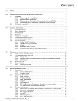
FIGURES Figure 1. Figure 2. Figure 3. Figure 4. Figure 5. Figure 6. Figure 7. Figure 8. Figure 9. Figure 10. Figure 11. Figure 12. Figure 13. Figure 14. Figure 15. Figure 16. Figure 17. Figure 18. Figure 19. Figure 20. Current profiles for 800GB models 24 Current profiles for 400GB models 25 Current profiles for 200GB models 25 Current profiles for 100GB models 26 800GB (at 6Gb) DC current and power vs. input/output operations per second 27 400GB (at 6Gb) DC current and power vs. input/output operations per second 27 200GB (at 6Gb) DC current and power vs. input/output operations per second 28 100GB (at 6Gb) DC current and power vs. input/output operations per second 28 Temperature check point location - 15mm drives 29 Temperature check point location - 7mm drives 29 Recommended mounting 30 Mounting configuration dimensions (800GB models 32 Mounting configuration dimensions (400, 200 & 100GB models 33 Example of FIPS tamper evidence labels 34 Physical interface 40 Air flow 41 Physical interface 53 SAS device plug dimensions 54 SAS device plug dimensions (detail 55 SAS transmitters and receivers 57 PULSAR.2 SAS PRODUCT MANUAL, REV. C IV

  • 1
  • 2
  • 3
  • 4
  • 5
  • 6
  • 7
  • 8
  • 9
  • 10
  • 11
  • 12
  • 13
  • 14
  • 15
  • 16
  • 17
  • 18
  • 19
  • 20
  • 21
  • 22
  • 23
  • 24
  • 25
  • 26
  • 27
  • 28
  • 29
  • 30
  • 31
  • 32
  • 33
  • 34
  • 35
  • 36
  • 37
  • 38
  • 39
  • 40
  • 41
  • 42
  • 43
  • 44
  • 45
  • 46
  • 47
  • 48
  • 49
  • 50
  • 51
  • 52
  • 53
  • 54
  • 55
  • 56
  • 57
  • 58
  • 59
  • 60
  • 61
  • 62
  • 63
  • 64
  • 65
  • 66
  • 67
  • 68
  • 69

P
ULSAR
.2 SAS P
RODUCT
M
ANUAL
, R
EV
. C
IV
F
IGURES
Figure 1.
Current profiles for 800GB models
. . . . . . . . . . . . . . . . . . . . . . . . . . . . . . . . . . . . . . . . . . . . . 24
Figure 2.
Current profiles for 400GB models. . . . . . . . . . . . . . . . . . . . . . . . . . . . . . . . . . . . . . . . . . . . . . 25
Figure 3.
Current profiles for 200GB models. . . . . . . . . . . . . . . . . . . . . . . . . . . . . . . . . . . . . . . . . . . . . . 25
Figure 4.
Current profiles for 100GB models. . . . . . . . . . . . . . . . . . . . . . . . . . . . . . . . . . . . . . . . . . . . . . 26
Figure 5.
800GB (at 6Gb) DC current and power vs. input/output operations per second . . . . . . . . . . .27
Figure 6.
400GB (at 6Gb) DC current and power vs. input/output operations per second . . . . . . . . . . .27
Figure 7.
200GB (at 6Gb) DC current and power vs. input/output operations per second . . . . . . . . . . .28
Figure 8.
100GB (at 6Gb) DC current and power vs. input/output operations per second . . . . . . . . . . .28
Figure 9.
Temperature check point location -
15mm drives . . . . . . . . . . . . . . . . . . . . . . . . . . . . . . . . . . 29
Figure 10.
Temperature check point location - 7mm drives . . . . . . . . . . . . . . . . . . . . . . . . . . . . . . . . . . .29
Figure 11.
Recommended mounting . . . . . . . . . . . . . . . . . . . . . . . . . . . . . . . . . . . . . . . . . . . . . . . . . . . . . 30
Figure 12.
Mounting configuration dimensions (800GB models) . . . . . . . . . . . . . . . . . . . . . . . . . . . . . . .32
Figure 13.
Mounting configuration dimensions (400, 200 & 100GB models) . . . . . . . . . . . . . . . . . . . . . .33
Figure 14.
Example of FIPS tamper evidence labels. . . . . . . . . . . . . . . . . . . . . . . . . . . . . . . . . . . . . . . . . 34
Figure 15.
Physical interface . . . . . . . . . . . . . . . . . . . . . . . . . . . . . . . . . . . . . . . . . . . . . . . . . . . . . . . . . . . 40
Figure 16.
Air flow . . . . . . . . . . . . . . . . . . . . . . . . . . . . . . . . . . . . . . . . . . . . . . . . . . . . . . . . . . . . . . . . . . . 41
Figure 17.
Physical interface . . . . . . . . . . . . . . . . . . . . . . . . . . . . . . . . . . . . . . . . . . . . . . . . . . . . . . . . . . . 53
Figure 18.
SAS device plug dimensions . . . . . . . . . . . . . . . . . . . . . . . . . . . . . . . . . . . . . . . . . . . . . . . . . . 54
Figure 19.
SAS device plug dimensions (detail) . . . . . . . . . . . . . . . . . . . . . . . . . . . . . . . . . . . . . . . . . . . . 55
Figure 20.
SAS transmitters and receivers . . . . . . . . . . . . . . . . . . . . . . . . . . . . . . . . . . . . . . . . . . . . . . . . 57