Sharp AR-RB1 Service Manual - Page 4
Attach the duplex bypass/inverter unit to the main, unit., Secure the duplex bypass/inverter unit.,
 |
View all Sharp AR-RB1 manuals
Add to My Manuals
Save this manual to your list of manuals |
Page 4 highlights
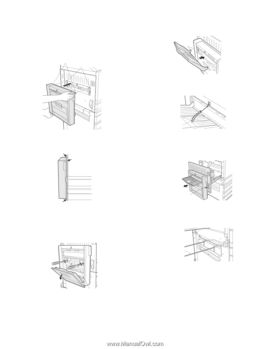
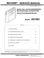
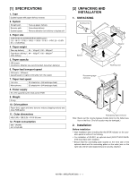
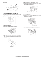
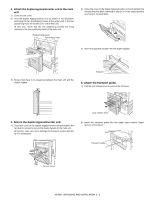
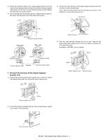
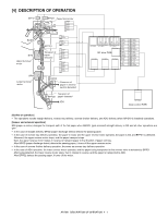
4. Attach the duplex bypass/inverter unit to the main unit. 1) Close the left cover. 2) Hold the duplex bypass/inverter unit as shown in the illustration and hang the two positioning bosses at the upper part in the two positioning holes on the left cover of the main unit. At this time, check that the two positioning bosses are hung securely in the two positioning holes of the main unit. Positioning bosses Positioning holes 2) Close the cover of the duplex bypass/inverter unit and reattach the exit tray that has been removed in step 2 in the raised position as shown in the illustration. 3) Insert the supplied actuator into the duplex bypass. 3) Ensure that there is no clearance between the main unit and the duplex bypass. Actuator 6. Attach the transport guide. 1) Pull the lock release lever to pull out the left cover. Lock release lever 5. Secure the duplex bypass/inverter unit. 1) Close the cover of the duplex bypass/inverter unit and tighten the two built-in screws to secure the duplex bypass to the main unit. At this time, take care not to damage the transport surface with the tip of a screwdriver. 2) Insert the transport guide into the paper input section (upper groove) of the stand. Transport guide Transport surface AR-RB1 UNPACKING AND INSTALLATION 2 - 3
-
 1
1 -
 2
2 -
 3
3 -
 4
4 -
 5
5 -
 6
6 -
 7
7 -
 8
8 -
 9
9 -
 10
10 -
11
-
12
-
13
-
14
-
15
-
16
-
17
-
18
-
19
-
20
-
21
-
22
-
23
-
24
-
25
-
26
-
27
-
28
-
29
-
30
-
31
-
32
-
33
-
34
-
35
-
36
 |
 |