Sharp ER-A330 Installation Manual - Page 5
Removing The, Printer Unit For, Er-a310 & Er-a330, Removing The Main,
 |
View all Sharp ER-A330 manuals
Add to My Manuals
Save this manual to your list of manuals |
Page 5 highlights
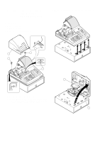
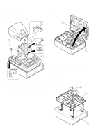
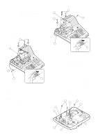
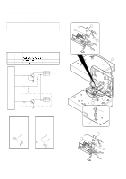
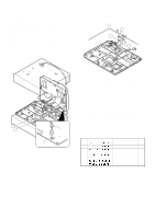
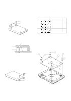
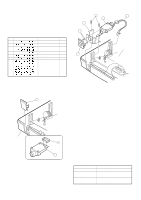
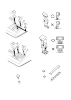
CHAPTER 5. REMOVING THE 2 PRINTER UNIT (For 5 ER-A310 & ER-A330) 2 1. ER-A310 1) Remove the top cabinet. 2) Remove the printer cable from the main PWB. 3) Remove the three screws . 4) Remove the screw ! and grounding wire ". 5) Remove the printer unit # from the top cabinet. 2 4 5 3 1 4 3 1 2. ER-A330 1) Remove the top cabinet. 2) Remove the printer cable from the main PWB. 3) Remove the three screws . 4) Remove the screw ! and grounding wire ". 5) Remove the printer unit # from the top cabinet. CHAPTER 6. REMOVING THE MAIN PWB (For ER-A310 & ER-A330) 1. ER-A310/A330 1) Remove the top cabinet. 2) Remove the printer unit. 3) Remove the following connector cables from the main PWB. Dry battery cable Pop up display cable Note: The pop-up cable is fixed with the holder not to make contact with the heat radiating plate on the main PWB. Be careful of it when installing. Mode switch cable ! Keyboard cable " 4) Remove the screw # and grounding wire $. 5) Remove the free screws % and main PWB &. 7 1 7 2 3 8 5 4 6 – 4 –
-
 1
1 -
 2
2 -
 3
3 -
 4
4 -
 5
5 -
 6
6 -
 7
7 -
 8
8 -
 9
9 -
 10
10
 |
 |
