Sharp ER-A330 Installation Manual - Page 9
One Hole Clerk, Key Kit, Key Top Kit
 |
View all Sharp ER-A330 manuals
Add to My Manuals
Save this manual to your list of manuals |
Page 9 highlights
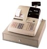
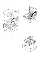
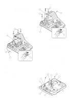
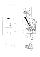
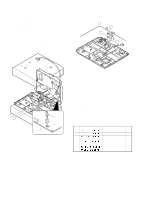
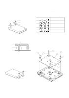
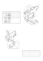
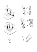
CHAPTER 10. ONE HOLE CLERK KEY KIT * Standard provision for the TQ, TR, and TS versions of the ERA330. 1. Component list No. PARTS CODE DESCRIPTION Q'ty 1 LKGIW7375BHZZ Clerk SW body 1 2 LKGIM7377BH01 Clerk key 1 2 3 LKGIM7377BH02 Clerk key 2 2 4 LKGIM7377BH03 Clerk key 3 2 5 LKGIM7377BH04 Clerk key 4 2 6 LKGIM7377BH05 Clerk key 5 2 7 LKGIM7377BH06 Clerk key 6 2 8 QCNW-7818BHZZ Clerk key cable (5P) 1 9 QCNCW2423BH0E Clerk connector (5P) 1 10 LANGT7602BHZZ Clerk switch angle 1 11 XJSSD26P08000 Screw 1 12 XEBSD30P08000 Screw 2 13 GFTAF6922BHZZ Clerk cover "B" 1 5 6 7 8 3 4 Main PWB. CN9 2. Installation procedure 1) Remove the top cabinet. 2) Remove the clerk cover "A" from the top cabinet. 3) Solder the clerk connector (5P) to the clerk switch body !. 1 7) Connect the clerk key cable (5P) " to location No. NC9 on the main PWB. 3. Operation test Top cabinet 2 3 4) Connect the clerk key cable (5P) " to the clerk switch body !. 5) Attach the clerk angle # to the clerk switch body ! and fix with screw $ (XJSSD26P08000). 6) Install the clerk switch body ! to the clerk cover "B" % then install it the top cabinet and fix with screws & (XEBSD30P08000). CHAPTER 11. KEY TOP KIT 1. Outline The ER-A460 employs the following key top (option) to allow additional installation of the key top and change in the key layout. MODEL NAME ER-11KT7 ER-12KT7 ER-22KT7 ER-11DK7 ER-51DK7 DESCRIPTION 1 × 1 Key top 1 × 2 Key top 2 × 2 Key top 1 × 1 Dummy key 5 × 1 Dummy key – 8 –
-
 1
1 -
2
-
3
-
 4
4 -
 5
5 -
 6
6 -
 7
7 -
 8
8 -
 9
9 -
 10
10
 |
 |
