Sharp ER-A330 Installation Manual - Page 6
Remote Drawer, Er-04dw For, Er-a310 & Er-a330 - parts
 |
View all Sharp ER-A330 manuals
Add to My Manuals
Save this manual to your list of manuals |
Page 6 highlights
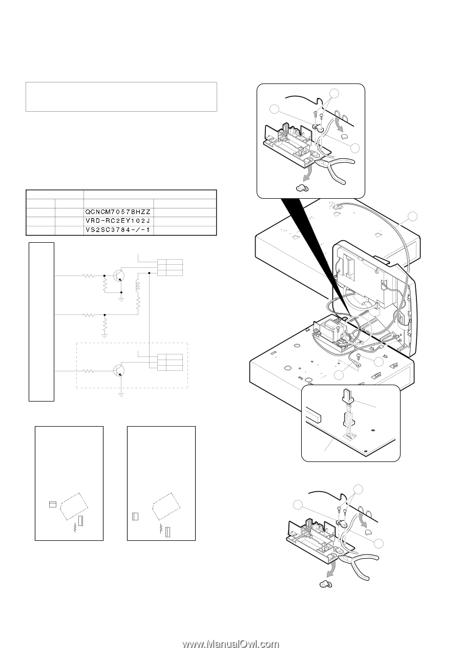
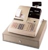
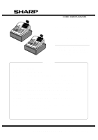
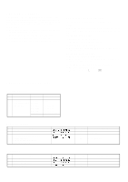
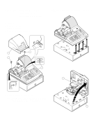
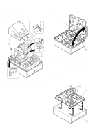
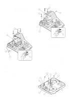
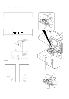
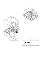
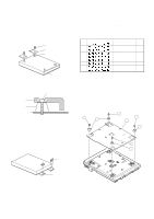
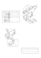
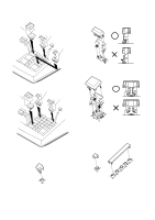
CHAPTER 7. REMOTE DRAWER: ER-04DW (For ER-A310 & ER-A330) CAUTION: The drawer unit should be securely fitted to the supporting platform to avoid instability when the drawer is open. 1. Outline The ER-A310/A330 allows connection of one remote drawer ER04DW. Note on the drawer connector The main PWB has no part for connection of the remote drawer. In order to connect the remote drawer, the following parts must be attached to the main PWB. LOCATION No. ER-A310 ER-A330 PARTS CODE DESCRIPTION CN16 CN16 QCNCM7057BHZZ Drawer connector R80 R89 VRD-RC2EY102J Resistor (1KΩ) Q20 Q20 VS2SC3784-/-1 Transistor (2SC3784) DR1 IC2 CPU JMS VP:+24V ER-A310:Q14 R53 1K ER-A330:Q21 C3784 R54 15K L2 R55 R56 15K 56K R57 ER-A310:3.3K ER-A330:4.7K CN11 STANDARD DRAWER DR2 ER-A310:R80 ER-A330:R89 1K VP:+24V CN16 ER-A310:Q20 ER-A330:Q14 C3784 OPTION DRAWER 5) Connect the drawer cable to the drawer connector on the main PWB. 6) Use nippers to cut off drawer cable binding holder on the trans cover, and bind drawer cable of the ER-04DW. Screw ! used in this case is an accessory of the ER-04DW. 3 1 2 ER-04DW 2 5 4 CN16 ER-A310 Main PWB ER-A330 Main PWB CN16 ICC2PU R80 1K Q20 C3784 CN16 ICC2PU R89 1K Q20 C3784 Main PWB. 7) Use nippers to cot off the drawer cable split pin of the top cabinet, and attach the top cabinet. 3 1 2 2. Installation procedure for ER-A310 1) Remove the top cabinet. 2) Remove the main PWB. 3) Solder the drawer connector CN16, the resistor (1kΩ) R80, and the transistor (2SC3784) Q20 to the main PWB. 4) Replace the main PWB. 8) Fix ground wire " of the ER-04DW on the standard drawer with screw #. Screw # used in this case is an accessory of the ER-04DW. – 5 –
-
 1
1 -
 2
2 -
 3
3 -
 4
4 -
 5
5 -
 6
6 -
 7
7 -
 8
8 -
 9
9 -
 10
10
 |
 |