Sharp LC-60LE810UN Service Manual - Page 17
ICON Unit, LED Unit, TOUCH SENSOR Unit, LED Panel, Module, Front Cabinet Ass'y, LCD Fixing, Metal
 |
UPC - 074000372580
View all Sharp LC-60LE810UN manuals
Add to My Manuals
Save this manual to your list of manuals |
Page 17 highlights
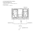
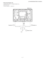
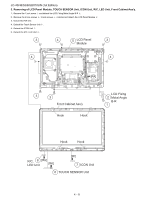
LC-40/46/52/60LE810UN (1st Edition) 3. Removing of LCD Panel Module, TOUCH SENSOR Unit, ICON Unit, R/C, LED Unit, Front Cabinet Ass'y. 1. Remove the 1 lock screw and detach the LCD Fixing Metal Angle B-R . 2. Remove the 5 lock screws , 3 lock screws , 4 Hooks and detach the LCD Panel Module 3. Disconnect RA wire. 4. Disconnect Touch Sensor Unit . 5. Detach the ICON Unit . 6. Detach the R/C, LED Unit . 3 4 LED Panel 5 Module 3 4 [RA] 3 3 3 Hook Hook LCD Fixing Metal Angle B-R 2 1 Hook Hook R/C, 8 [RA] [RK] LED Unit [RI] Front Cabinet Ass'y 7 ICON Unit 6 TOUCH SENSOR Unit 4 - 3
-
 1
1 -
2
-
3
-
4
-
5
-
6
-
7
-
8
-
9
-
10
-
11
-
 12
12 -
 13
13 -
 14
14 -
 15
15 -
 16
16 -
 17
17 -
 18
18 -
 19
19 -
 20
20 -
 21
21 -
 22
22 -
23
-
24
-
25
-
26
-
27
-
28
-
29
-
30
-
31
-
32
-
33
-
34
-
35
-
36
-
37
-
38
-
39
-
40
-
41
-
42
-
43
-
44
-
45
-
46
-
47
-
48
-
49
-
50
-
51
-
52
-
53
-
54
-
55
-
56
-
57
-
58
-
59
-
60
-
61
-
62
-
63
-
64
-
65
-
66
-
67
-
68
-
69
-
70
-
71
-
72
-
73
-
74
-
75
-
76
-
77
-
78
-
79
-
80
-
81
-
82
-
83
-
84
-
85
-
86
-
87
-
88
-
89
-
90
-
91
-
92
-
93
-
94
-
95
-
96
 |
 |

LC-40/46/52/60LE810UN (1st Edition)
4 – 3
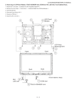
3. Removing of LCD Panel Module, TOUCH SENSOR Unit, ICON Unit, R/C, LED Unit, Front Cabinet Ass’y.
1.
Remove the 1 lock screw
and detach the LCD Fixing Metal Angle B-R
.
2.
Remove the 5 lock screws
, 3 lock screws
, 4 Hooks and detach the LCD Panel Module
3.
Disconnect RA wire.
4.
Disconnect Touch Sensor Unit
.
5.
Detach the ICON Unit
.
6.
Detach the R/C, LED Unit
7
ICON Unit
8
R/C,
LED Unit
6
TOUCH SENSOR Unit
5
LED Panel
Module
Front Cabinet Ass'y
3
4
4
3
3
3
3
1
[RI]
[RK]
[RA]
[RA]
2
Hook
Hook
Hook
Hook
LCD Fixing
Metal Angle B-R