Sharp PN-H701 Operations Manual - Page 33
Control command table, Power control/Input mode selection, PICTURE menu
 |
View all Sharp PN-H701 manuals
Add to My Manuals
Save this manual to your list of manuals |
Page 33 highlights
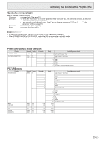
Controlling the Monitor with a PC (RS-232C) Control command table How to read the command table Command: Direction: Parameter: Reply: Command field (See page 31.) W When the "Parameter" is set in the parameter field (see page 31), the command functions as described under "Control/Response Contents". R The returned value indicated under "Reply" can be obtained by setting "????" or "? " in the parameter field (see page 31). Parameter field (See page 31.) Response (Returned value) TIPS • In the power standby state, the only command that is used is POWER CONTROL. • When STANDBY MODE is LOW POWER, control via LAN is not possible in standby mode. Power control/Input mode selection Function POWER CONTROL INPUT MODE SELECTION Command Direction POWR WR ITGD W IAVD WR Parameter 0 1 0 1 2 3 4 5 6 PICTURE menu Function PICTURE MODE Command Direction AVMD W R Parameter 0 1 2 3 6 7 9 11 20 BRIGHT CONTRAST BLACK LEVEL TINT COLORS SHARPNESS VLMP WR CONT WR BLVL WR TINT WR COLR WR SHRP WR -16-16 0-40 -30-30 -30-30 -30-30 0-20 Reply Control/Response contents 0 Switches to standby mode. 1 Returns from standby mode. Toggle change for input mode. 1 HDMI1 2 HDMI2 3 HDMI3 4 HDMI4 5 D-SUB 6 MULTIMEDIA (USB port/Internal memory) Reply Control/Response contents Toggle change for input mode. AV MOVIE GAME DYNAMIC PC sRGB PHOTO HIGH RESOLUTION 1 AV 2 MOVIE 3 GAME 6 DYNAMIC 7 PC 9 sRGB 11 PHOTO 20 HIGH RESOLUTION -16-16 0-40 -30-30 -30-30 -30-30 0-20 33 E
-
 1
1 -
2
-
3
-
4
-
5
-
6
-
7
-
8
-
9
-
10
-
11
-
12
-
13
-
14
-
15
-
16
-
17
-
18
-
19
-
20
-
21
-
22
-
23
-
24
-
25
-
26
-
27
-
 28
28 -
 29
29 -
 30
30 -
 31
31 -
 32
32 -
 33
33 -
 34
34 -
 35
35 -
 36
36 -
 37
37 -
 38
38 -
39
-
40
-
41
-
42
-
43
-
44
-
45
-
46
-
47
-
48
-
49
-
50
-
51
-
52
-
53
-
54
-
55
-
56
-
57
-
58
-
59
-
60
 |
 |
