Sharp R930AK Service Manual - Page 18
˚F20˚C - 86˚F30˚C - price
 |
UPC - 074000606036
View all Sharp R930AK manuals
Add to My Manuals
Save this manual to your list of manuals |
Page 18 highlights
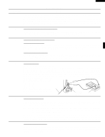
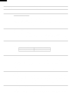
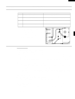
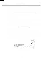
R-930AK R-930AW PROCEDURE LETTER TEST PROCEDURES COMPONENT TEST An open temperature fuse indicates overheating of the magnetron assembly, check for restricted air flow to the magnetron through the opening in the chassis, especially the cooling duct and cooling fan. J THERMAL CUT-OUT TEST A continuity check across the thermal cut-out terminals should indicate a closed circuit unless the temperature of thermal cut-out reaches 302˚F(150˚C). The thermal cut-out resets automatically at approximately 266˚F(130˚C). If the thermal cut-out has opened under the normal condition, replace the same item as in the parts list. An open thermal cut-out indicates overheating of heater unit. Check for restricted air flow to the heater unit through the vent hole of the oven cavity, especially the heater duct and convection fan. K HEATING ELEMENT TEST Make sure the heating element is fully cooled and test as follows; a. Disconnect wire leads and measure the resistance with an ohmmeter. On the R x 1 scale, the resistance between the heating element terminals should be approximately 10.2Ω. b. Disconnect wire leads and measure the insulation resistance with 500V - 100MΩ insulation resistance meter. The insulation resistance between heating element terminal and cavity should be more than 0.5MΩ. L THERMISTOR TEST Disconnect connector-E from the control unit. Measure the resistance of the thermistor with an ohmmeter. Connect the ohmmeter leads to Pin No's E-3 and E-4. Room Temperature 68˚F(20˚C) - 86˚F(30˚C) Resistance Approx. 350kΩ - 155KΩ If the meter does not indicate above resistance, replace the thermistor M DAMPER MOTOR TEST When the power cord is plugged into the wall receptacle and 120 volts A.C. is supplied to the damper motor, the motor operates until the damper is opened and the damper switch closes. Then the damper motor stops operation. If the damper motor does not operate, check for A.C. voltage with a voltmeter at the motor. 1. Disconnect the power cord from the wall receptacle. 2. Disconnect the wire leads of motor and connect the meter leads to the wire leads of main wire harness. 3. Re-connect the power cord into the wall receptacle. If 120 volts A.C. is indicated at the wire leads, replace the motor and if 120 volts A.C. is not indicated, check the wire harness and control unit. N DAMPER SWITCH TEST Disconnect the wire leads from the switch terminals and connect ohmmeter leads to the common (COM.) and normally open (N.O.) terminals of the switch. 1. When switch actuator is pushed by the damper motor cam, the meter should be indicated a closed circuit. 2. When power cord is plugged into the wall receptacle, the damper motor operates and damper cam will start to rotate. When the switch actuator is released, the meter should be indicated an open circuit. If improper operation is indicated, replace the damper switch. O CHECKING TEMPERATURE IN THE CONVECTION MODE It is difficult to measure the exact temperature in the convection oven. An accurate thermocouple type temperature tester must be used. A low priced bi-metal type thermometer is not reliable or accurate. The temperature should be checked with outer case cabinet installed, approx. 5 minutes after preheat 16
-
 1
1 -
2
-
3
-
4
-
5
-
6
-
7
-
8
-
9
-
10
-
11
-
12
-
 13
13 -
 14
14 -
 15
15 -
 16
16 -
 17
17 -
 18
18 -
 19
19 -
 20
20 -
 21
21 -
 22
22 -
 23
23 -
24
-
25
-
26
-
27
-
28
-
29
-
30
-
31
-
32
-
33
-
34
-
35
-
36
-
37
-
38
-
39
-
40
-
41
-
42
-
43
-
44
 |
 |