Sharp R930AK Service Manual - Page 24
Description Of Lsi - built in
 |
UPC - 074000606036
View all Sharp R930AK manuals
Add to My Manuals
Save this manual to your list of manuals |
Page 24 highlights
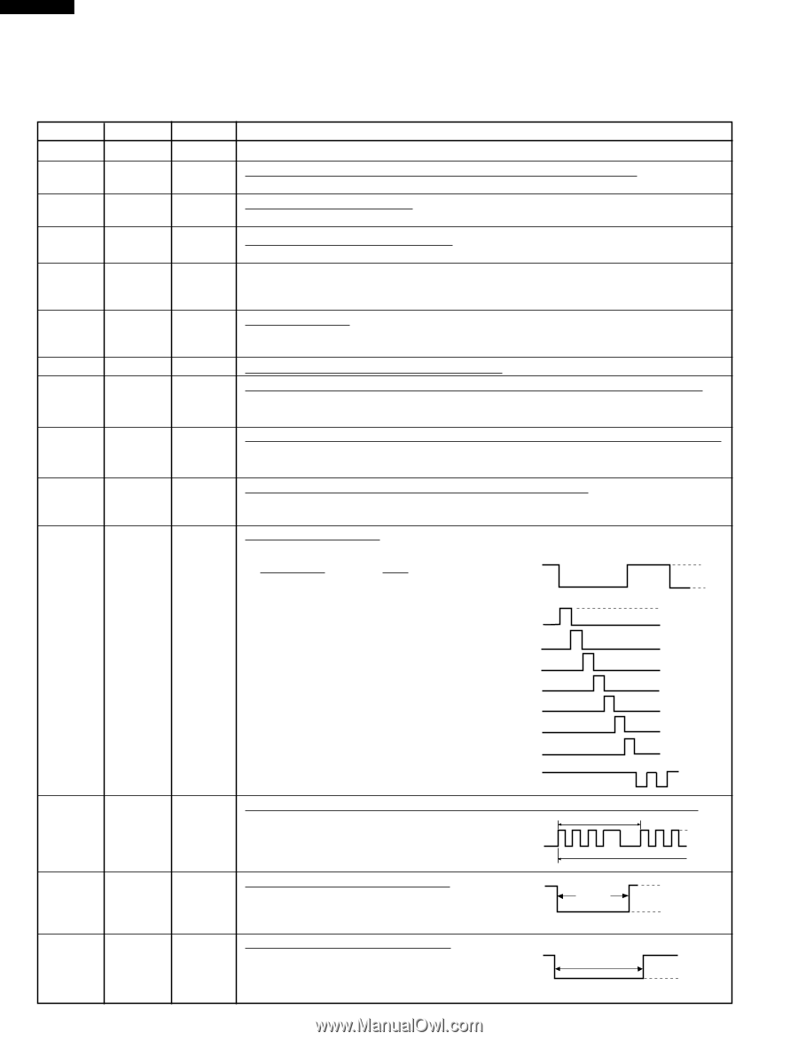
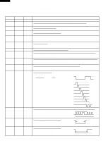
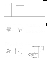
R-930AK R-930AW DESCRIPTION OF LSI LSI(IZA797DR): The I/O signals of the LSI(IZA797DR) are detailed in the following table. Pin No. 1 2 Signal VCC VEE 3 AVSS 4 VREF 5 AN7 6 AN6 7-9 AN5-AN3 10 AN2 11 AN1 12 AN0 13 P55 14 P54 I/O IN IN IN IN IN IN IN IN IN IN OUT OUT Description Connected to GND. Anode (segment) of Fluorescent Display light-up voltage: -30V. Vp voltage of power source circuit input. Power source voltage: -5V. VC voltage of power source circuit input. Reference voltage input terminal. A reference voltage applied to the A/D converter in the LSI. Connected to GND.(0V) Used for initial balancing of the bridge circuit (absolute humidity sensor). This input is an analog input terminal from the AH sensor circuit, and connected to the A/D converter built into the LSI. AH sensor input. This input is an analog input terminal from the AH sensor circuit, and connected to the A/D converter built into the LSI. Heating constant compensation terminal. Input signal which communicates the door open/close information to LSI. Door closed; "H" level signal(0V). Door opened; "L" level signal(-5V). Input signal which communicates the damper open/close information to LSI. Damper opened; "H" level signal(0V:GND). Damper closed; "L" level signal(-5V). Temperature measurement input: OVEN THERMISTOR. By inputting DC voltage corresponding to the temperature detected by the thermistor, this input is converted into temperature by the A/D converter built into the LSI. Digit selection signal. The relationship between digit signal and digit are as follows; Digit signal Digit H ß(60Hz) P03 1st. L P02 2nd. GND P03 VP P01 3rd. P00 4th. P02 P01 P37 5th. P00 P36 6th. P37 P35 7th. P36 P55 8th. Normally, one pulse is output in every ß P35 period, and input to the grid of the Fluores- P55 cent Display. Oven lamp and turntable motor driving signal. (Square Waveform : 60Hz) To turn on and off the shut-off relay(RY1). 16.7 msec. The square waveform voltage is delivered to H the relay(RY1) driving circuit. L During cooking 15 P53 OUT Convection motor driving signal. To turn on and off shut-off relay(RY5). "L" During cooking H. GND OFF level during CONVECTION; "H" level other- (Convection) ON L wise. 16 P52 OUT Cooling fan motor driving signal. To turn on and off shut-off relay(RY6). "L" level during both microwave and convection cooking; "H" level otherwise. During cooking ON OFF H. GND L 22
-
 1
1 -
2
-
3
-
4
-
5
-
6
-
7
-
8
-
9
-
10
-
11
-
12
-
13
-
14
-
15
-
16
-
17
-
18
-
 19
19 -
 20
20 -
 21
21 -
 22
22 -
 23
23 -
 24
24 -
 25
25 -
 26
26 -
 27
27 -
 28
28 -
 29
29 -
30
-
31
-
32
-
33
-
34
-
35
-
36
-
37
-
38
-
39
-
40
-
41
-
42
-
43
-
44
 |
 |